Petroleum pipeline plugging device

A plugging device, oil pipeline technology, applied in the direction of pipe components, pipes/pipe joints/pipe fittings, mechanical equipment, etc., can solve the problems of pipe instrument blockage, large resource consumption, pipeline pollution, etc., to prevent accidents and reduce preparation work , the effect of improving safety

Active Publication Date: 2018-10-26
李得恩
View PDF5 Cites 1 Cited by
  • Summary
  • Abstract
  • Description
  • Claims
  • Application Information

AI Technical Summary

Problems solved by technology

(2) The rubber ball plugging method is also called pigging ball: this method is to place an inflatable rubber isolation ball at both ends of the pipeline that needs to be repaired, and cooperate with the butter wall to play the role of sealing and isolation, and the operation is completed Finally, the isolation ball needs to be taken out. The disadvantage is that the rubber isolation ball must be able to be taken out. In the process of taking it out, the rubber isolation ball needs to be destroyed. The damaged rubber residue will pollute the pipeline and also cause blockage to the instrument on the pipeline.
(3) Freezing plugging method: This method is to fill the inside of the pipeline that needs to be replaced with water, and use refrigeration equipment to freeze two sections of icicles in the pipeline, so as to play the role of sealing. The disadvantage is that a lot of preparation work is required before operation , It needs to consume a lot of resources. If it takes a long time to freeze in high temperature seasons, and in cold areas, it will take a long time for the icicles to completely melt after the operation is completed, resulting in a waste of resources.

Method used


Image

  • Petroleum pipeline plugging device
  • Petroleum pipeline plugging device
  • Petroleum pipeline plugging device

Examples


Embodiment 1

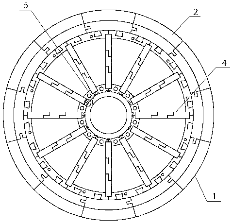
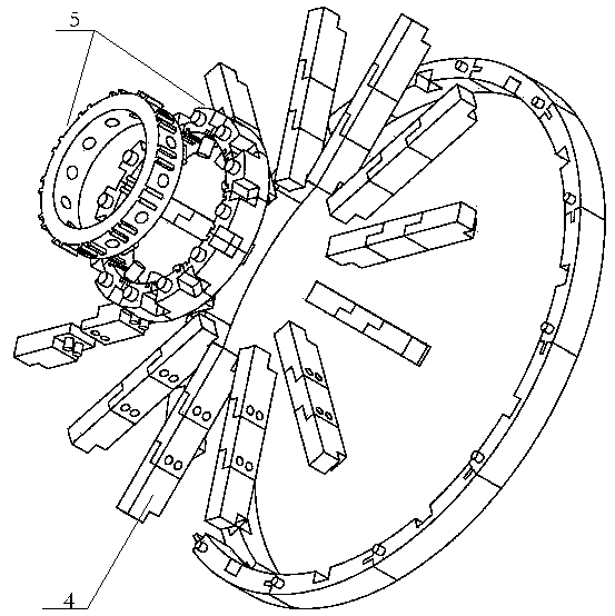
[0033] Such as Figure 1-3 As shown, an oil pipeline plugging device related to the present invention includes a plugging part, and the plugging part is assembled from a plurality of pluggable plugging parts, and the plugging parts are provided with A plug-in structure that cooperates with each other, and the plurality of plugging parts are connected through a set of plug-in structures that cooperate with each other. The side of the part is also provided with a rib-shaped sealant, and the side of the sealant close to the opening of the pipeline to be repaired is provided with a groove, and the sealing part between the baffle and the end opening is also provided with a In the interfitting plug-in structure, at least one side of the blocking part body parts extends outward along a direction forming a certain angle with the generatrix of the blocking part to form a flexible or elastic edge with elasticity or flexibility, The sealing part and the set flexible or elastic edge form...

Embodiment 2

[0046] Such as Figure 4-7 As shown, the present invention relates to a petroleum-soluble umbrella-shaped occluder, which includes a bolt-shaped sealing part made of petroleum-soluble materials, and the pressure-receiving part is cylindrical and contains an inner hollow part, a circular Cylindrical sealant composition. The plugging part, the pressure receiving part and the sealant are all made of petroleum-soluble materials. The plugging part moves toward the pressure-bearing part under the pressure generated in the pipeline, and the sealant is squeezed when moving. After the sealant is squeezed, it fills the small gap between the plugging part and the pressure-bearing part and the inner wall of the pipe, and connects the plugging part and the bearing The small gap between the edge of the pressure part and the inner wall of the pipe is tightly sealed. The plugging part is forced to move backward, and the screw-shaped protrusion designed by the bolt-shaped plugging part is st...


PUM


Abstract

The invention provides a petroleum pipeline plugging device. The petroleum pipeline plugging device comprises a plugging part which is matched with a to-be-maintained pipeline in shape, wherein the bottom of one side, away from an opening part of the to-be-maintained pipeline, of the plugging part is sealed; flange shaped sealant is further arranged on the side surface of the plugging part; a groove is formed in the side surface of one side, close to the opening part of the to-be-maintained pipeline, of the sealant; and both the plugging part and the sealant are made of a material which can bedissolved into petroleum. The petroleum pipeline plugging device has the beneficial effects of high efficiency and high safety.

Description

Technical field: [0001] The invention relates to an oil pipeline sealing device. Background technique: [0002] At present, pipelines for transporting flammable and explosive substances such as natural gas and oil need to be replaced and repaired after a period of use due to corrosion of the pipelines, and welding and hot work are required during replacement and maintenance. During hot welding operations, if flammable and explosive substances cannot be effectively isolated, major explosion and combustion accidents will occur. In the past, the main ways to seal the pipeline are: (1) The butter sealing method is also called the butter wall: this method is to push a certain amount of butter at both ends of the pipeline that needs to be repaired to form a butter column to play a sealing role. The function of blocking and isolation, the disadvantage is that the operator needs to complete the welding hot work in a short time, otherwise the butter will collapse and fail, the butte...

Claims


Application Information

Patent Timeline
Patent Type & Authority Applications(China)
IPC IPC(8): F16L55/11
CPCF16L55/1141
Inventor 李得恩王军吕春雷杨卓张宏涛
Owner 李得恩
Why Eureka
Try Eureka