Nitrogen cooling tower

A nitrogen cooling, nitrogen technology, applied in water shower coolers, direct contact heat exchangers, heat exchanger types, etc., can solve problems such as poor cooling effect and slow cooling speed, and reduce maintenance and cleaning workload , Easy to operate, effective control of nitrogen flow rate

Pending Publication Date: 2018-10-26
JIANGYIN CHEM MASCH CO LTD
View PDF8 Cites 4 Cited by
  • Summary
  • Abstract
  • Description
  • Claims
  • Application Information

AI Technical Summary

Problems solved by technology

The core equipment in the nitrogen cooling device is the nitrogen cooling tower. Its general design structure is: shell, filler grid, filler, ear seat, spray device, upper pressure gauge port, nozzle components, etc., and there is always a cooling tower. Issues with slow speed and poor cooling

Method used


Image

  • Nitrogen cooling tower
  • Nitrogen cooling tower
  • Nitrogen cooling tower

Examples


Embodiment Construction

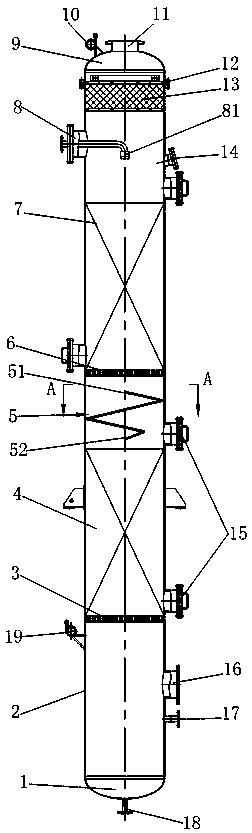
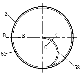
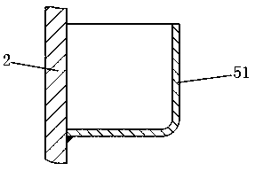
[0015] The specific implementation manners of the present invention will be further described in detail below in conjunction with the accompanying drawings.

[0016] Such as Figure 1~4 As shown, the present invention includes a cylinder body 2, an upper head 9 and a lower head 1 are fixedly arranged at the upper and lower ends of the cylinder 2, the lower head 1 is provided with a cooling water outlet 18, and the upper head 9 is provided with nitrogen gas The outlet 11 and the upper pressure gauge interface 10, the second filler 7, the second filler grid 6, the deflector 5, the first filler 4, and the first filler grid 3 are sequentially arranged in the cylinder body 2 from top to bottom. Both the second filler 7 and the first filler 4 adopt Pall rings, and the cylinder 2 above the second filler 7 is provided with a spray device 8, and the spray head 81 of the spray device 8 extends to the center of the cylinder 2, and the first filler A nitrogen inlet 16 and a lower pressur...


PUM


Abstract

The invention relates to a nitrogen cooling tower. The nitrogen cooling tower is characterized by comprising a barrel, an upper sealing head and a lower sealing head, a cooling water outlet is formedin the lower sealing head, a nitrogen outlet and an upper pressure meter connector are arranged on the upper sealing head, a second padding, a second padding grating, a flow guide plate, a first padding and a first padding grating are sequentially arranged in the barrel from top to bottom, a spraying device is arranged above the second padding, a spraying head of the spraying device extends to themiddle of the barrel, and a nitrogen inlet and a lower pressure meter connector are arranged below the first padding grating; the flow guide plate comprises an angle iron section and a box iron section, the angle iron section is formed by spirally welding angle iron to the inner wall of the barrel, the box iron section is bent into semicircular box iron, and the box iron section is welded to thelower end of the angle iron section and extends to the center of the barrel. The nitrogen cooling tower is simple and compact in structure, the nitrogen flowing speed is effectively controlled, the nitrogen purity and the cooling speed are increased, meanwhile, padding in the tower can be subjected to in-time cleaning, detecting and equipment maintaining in a staged manner, and the maintaining andcleaning working loads are reduced.

Description

technical field [0001] The invention relates to a nitrogen cooling tower. Background technique [0002] At present, with the increase of production scale, the domestic chemical fiber industry gradually eliminates the relatively backward "intermittent drying" and adopts the "continuous drying" process of sustainable production. The cooling of slices in continuous drying is mainly done by cold nitrogen. The core equipment in the nitrogen cooling device is the nitrogen cooling tower. Its general design structure is: shell, filler grid, filler, ear seat, spray device, upper pressure gauge port, nozzle components, etc., and there is always a cooling tower. Problems with slow speed and poor cooling. Contents of the invention [0003] In view of the above problems, the applicant has carried out research and improvement, and provides a nitrogen cooling tower, which has a simple and compact structure, is easy to operate, can effectively control the flow rate of nitrogen, improve ...

Claims


Application Information

Patent Timeline
Patent Type & Authority Applications(China)
IPC IPC(8): F28C1/00F28F25/10
CPCF28C1/00F28F25/10
Inventor 陈少忠李奇英
Owner JIANGYIN CHEM MASCH CO LTD
Why Eureka
Try Eureka