Adjustable magnetic ring

An adjustable, magnetic ring technology, applied in the direction of magnets, magnetic objects, measuring device magnets, etc., can solve the problems of weakened shielding and impurity removal performance, poor noise removal, and enhanced electromagnetic radiation, etc., to reduce test costs , Reduce test time and the effect of misjudgment rate

Inactive Publication Date: 2018-10-26
ZHENGZHOU YUNHAI INFORMATION TECH CO LTD
View PDF5 Cites 2 Cited by
  • Summary
  • Abstract
  • Description
  • Claims
  • Application Information

AI Technical Summary

Problems solved by technology

[0006] During the radiation test, the frequency range of 30Mhz-300Mhz is mainly to consider the shielding and noise removal of the wire, and with the increase of the frequency and age of the wire, the internal line loss gradually decreases, which leads to its shielding and impurity removal performance. It is greatly weakened, and the fixed magnetic ring on the wire and the existing magnetic ring are limited by materials, parameters, cross-sectional area and materials, which cannot remove noise well, resulting in noise and wire coupling to form a radiation antenna, enhancing Electromagnetic radiation, causing the product to fail during the radiation test (Fail)

Method used


Image

  • Adjustable magnetic ring
  • Adjustable magnetic ring
  • Adjustable magnetic ring

Examples


Embodiment 1

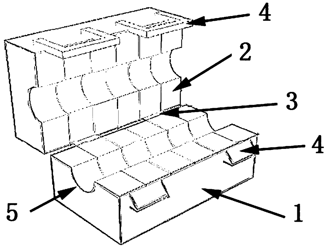
[0026] like Figure 1~5 As shown, an adjustable magnetic ring includes:

[0027] A casing and several half-cores placed in the casing, the casing 1 includes an upper part and a lower part. The half magnetic cores 2 are matched in pairs to form a complete magnetic core and can be arranged in the housing.

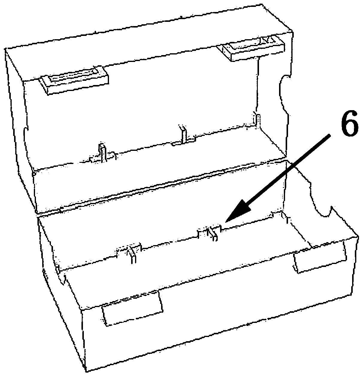
[0028] The upper part and the lower part of the casing 1 are hinged together by a plastic connecting piece 3 , and the other end is provided with a snap 4 , and the upper part and the lower part are snapped together by the snap 4 . The casing 1 in this embodiment is provided with a semicircular notch 5 . A limiting device 6 is arranged inside the casing. The limiting device 6 is used to limit the position of the half core 2 .

[0029] The combined radiation test results of an adjustable magnetic ring and half magnetic core are as follows: Image 6 , the horizontal line in the figure is the test standard specification line, and the dark and light curves represent the vert...


PUM


Abstract

Embodiments of the present invention provide an adjustable magnetic ring. The adjustable magnetic ring includes a housing and a plurality of semi-magnetic cores disposed in the housing; the housing includes an upper portion and a lower portion; every two semi-magnetic cores are coupled to form a complete magnetic core, and the complete magnetic cores are arranged in the housing; one ends of the upper portion and the lower portion of the housing are hinged, and fasteners are arranged on the other ends of the upper portion and the lower portion; the upper portion and the lower portion are fastened together through the fasteners. The adjustable magnetic ring is adjustable in magnetic ring material, cross-sectional area, and length. The most effective magnetic ring for noise is determined according to the magnetic ring material, the cross-sectional area, and the length. The upper portion and the lower portion of the housing are hinged through plastic connection members, and the flexibilityof the housing is improved. The other ends of the upper portion and the lower portion of the housing are connected through the fasteners, the upper semi-magnetic ring and the lower semi-magnetic ringcan be lap-jointed well to form a whole body, and gaps between the upper and lower magnetic cores can be prevented.

Description

technical field [0001] The invention relates to the field of magnetic ring design. Background technique [0002] In order to suppress noise, ferromagnetic materials are widely used in EMC. When applied to EMC testing, all ferromagnetic materials have 3 properties: (1) saturation; (2) frequency response; (3) ability to concentrate magnetic flux. [0003] (1) Saturation: The current I flows through the coil, and the current generates a magnetic field strength H, which is proportional to the product NI of the number of coil turns and the current. In this way, a magnetic flux density B is generated in the magnetic field, and B is multiplied by the cross-sectional area of ​​the magnetic core to obtain the magnetic flux. When the current is small, the magnetic flux is large; as the current increases, the magnetic flux rate decreases. This is the phenomenon in which the flux rate of a ferromagnetic core decreases as the current increases, called saturation. [0004] (2) Ability...

Claims


Application Information

Patent Timeline
Patent Type & Authority Applications(China)
IPC IPC(8): G01R1/16H01F7/00
CPCG01R1/16H01F7/00
Inventor 吴鑫胡志超
Owner ZHENGZHOU YUNHAI INFORMATION TECH CO LTD
Why Eureka
Try Eureka