Method for measuring antiferromagnetic domain distribution by using magneto-optic Kerr effect

A magneto-optic Kerr effect and antiferromagnetic technology, applied in the field of physical measurement, can solve the problems of antiferromagnetic material damage, experiment time and place limitations, and restrict the progress of antiferromagnetic materials, and achieve the effect of reducing equipment costs

Active Publication Date: 2018-10-26
FUDAN UNIV
View PDF6 Cites 4 Cited by
  • Summary
  • Abstract
  • Description
  • Claims
  • Application Information

AI Technical Summary

Problems solved by technology

However, the means to detect antiferromagnetic materials has been relatively scarce.
[0003] At present, the research on the magnetic domain structure of antiferromagnetic materials mainly relies on photoelectron microscopy with the help of X-ray magnetic line dichroism effect, but this method needs to rely on X-rays of specific wavelengths, and such X-rays can only be obtained from different sources in the country. The acquisition of more than five synchrotron radiation sources will be greatly restricted in terms of experiment time and location
At the same time, since the photoelectron microscope needs to image the electron beam, it is impossible to introduce current and magnetic field at the same time as the measurement
Although some people have also used femtosecond lasers to detect antiferromagnetic directions by means of pump-probe methods, but the price of femtosecond lasers is also very expensive, and the detection takes a long time, and high-intensity pump lasers may also Destruction of the antiferromagnetic material itself
These limitations largely restrict the progress of research on antiferromagnetic materials.

Method used


Image

  • Method for measuring antiferromagnetic domain distribution by using magneto-optic Kerr effect
  • Method for measuring antiferromagnetic domain distribution by using magneto-optic Kerr effect
  • Method for measuring antiferromagnetic domain distribution by using magneto-optic Kerr effect

Examples


Embodiment

[0032] Measuring antiferromagnetic domains using this method requires a magneto-optical Kerr microscope with digital image acquisition capabilities.

[0033] The specific measurement steps are:

[0034] 1. Move the polarizer first, so that the overall brightness of the image is the lowest, so that the extinction position is found;

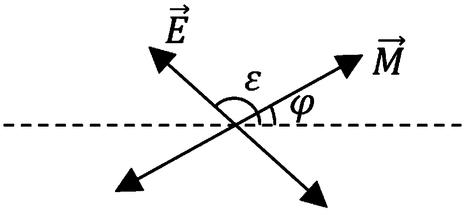
[0035] 2. Then rotate the polarizer clockwise by a certain angle α, so that the brightness of the image increases to an appropriate size, and collect an image (such as figure 2 );

[0036] 3. Then rotate the polarizer in the opposite direction by an angle of 2α. During this process, the overall brightness of the image will first decrease and then increase to be similar to the first image, and then collect the second image (such as image 3 ).

[0037] Subsequently, the computer program is used to process the image to obtain the magnetic domain information (the program flow chart is as follows Figure 4 shown):

[0038] 1. Use a Gaussian filte...


PUM


Abstract

The invention belongs to the technical field of physical measurement, and particularly provides a method for measuring antiferromagnetic domain distribution by using the magneto-optic Kerr effect. A magneto-optic Kerr microscope having the function of acquiring the digital image is used. The measurement process comprises the steps of data acquisition: a polarizer acting as a polarization analyzeris controlled to deviate the same angle to the clockwise or anticlockwise direction in the extinction position so as to acquire two images of the sample surface; data analysis: firstly the two acquired images are blurred and all the magnetic domain information is removed and only the uneven light intensity information of the sample surface is reserved and then the contribution of the uneven lightintensity is eliminated out of the two original images so as to obtain the mixed signals of the shape and magnetic domain information of the two samples; and then subtraction and other processing areperformed so as to obtain the antiferromagnetic domain distribution of the sample surface. The method has low cost and provides multiple possible directions for the research of the antiferromagnetic materials.

Description

technical field [0001] The invention belongs to the technical field of physical measurement, and in particular relates to a method for measuring antiferromagnetic domains using a magneto-optical Kerr microscope. Background technique [0002] Due to their stability under external magnetic fields, antiferromagnetic materials are widely used in existing spintronic devices (such as mechanical hard disks) and future devices (such as magnetic random access memory). Especially in recent years, after it was discovered that antiferromagnetic materials can also store information, and antiferromagnetic magnetic moments can be manipulated by electric current, antiferromagnetic materials have begun to receive more and more attention. However, the means to detect antiferromagnetic materials has been relatively scarce. [0003] At present, the research on the magnetic domain structure of antiferromagnetic materials mainly relies on photoelectron microscopy with the help of X-ray magnetic ...

Claims


Application Information

Patent Timeline
Patent Type & Authority Applications(China)
IPC IPC(8): G01R33/032G01R33/10
CPCG01R33/0325G01R33/10
Inventor 周超许佳贾孟文吴义政
Owner FUDAN UNIV
Why Eureka
Try Eureka