
Solar cell string structure

A technology of solar cells and batteries, applied in circuits, photovoltaic power generation, electrical components, etc., can solve problems such as inability to remove battery ribbons, require high welding precision, and affect the aesthetics of components, so as to achieve no optical loss and increase power generation , the effect of area reduction

Inactive Publication Date: 2018-10-26
LONGI SOLAR TECH (TAIZHOU) CO LTD
View PDF4 Cites 1 Cited by
  • Summary
  • Abstract
  • Description
  • Claims
  • Application Information

AI Technical Summary

Problems solved by technology

But first of all, the multi-busbar technology uses circular ribbons to connect the cells, which requires high welding precision. During the welding process, it is easy to have poor appearance such as offset and skew of the ribbons.
Secondly, the multi-busbar technology still needs to be connected by ribbons, which also shield the cells to a certain extent, and the series resistance of the modules is still large;
[0004] In the prior art, battery slices whose front and back are perpendicular to each other are placed at the end of the battery string, and the bus bar at one end of the module can be removed, such as Figure 4 As shown in the figure, this way of placing the battery slices perpendicular to each other at the end of the battery string can remove the bus bar at one end of the module, but the solder ribbon on the battery slice cannot be removed, and the optical and electrical losses caused by the solder ribbon on the battery slice It still exists. In addition, placing two different cells on the same module affects the aesthetics of the module

Method used


Image

  • Solar cell string structure
  • Solar cell string structure
  • Solar cell string structure

Examples


Embodiment Construction

[0021] The present invention is further described below in conjunction with accompanying drawing:

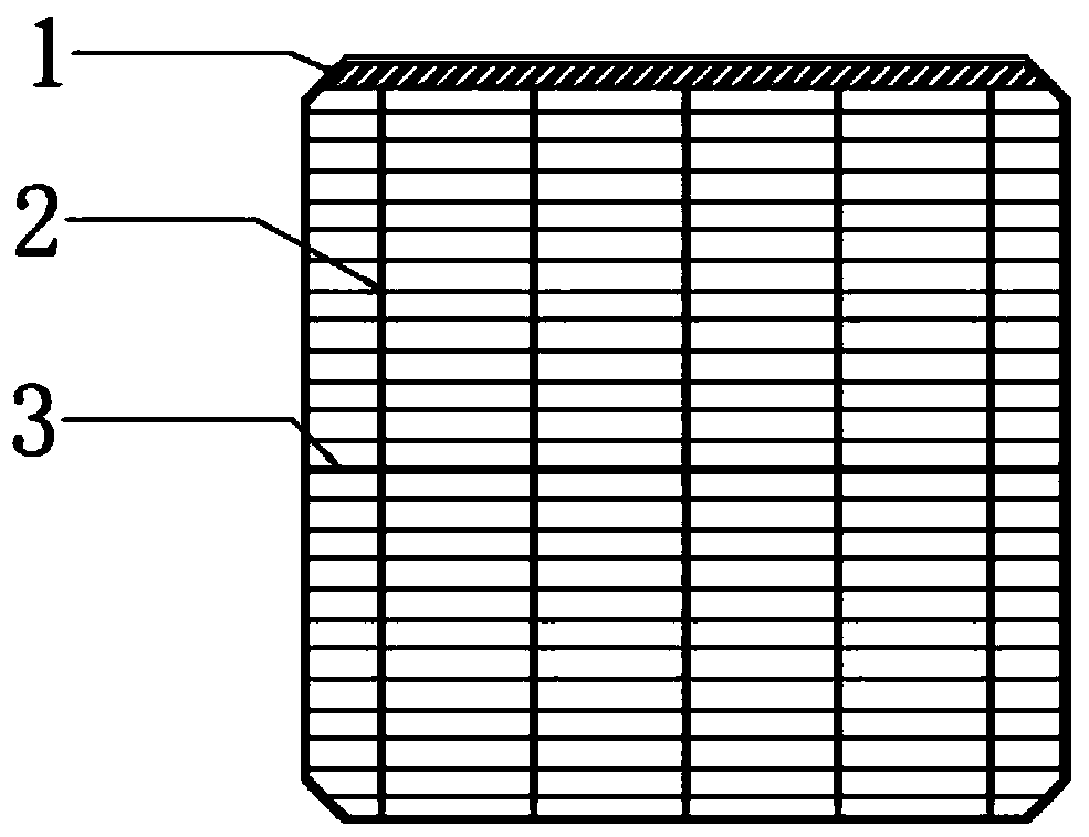
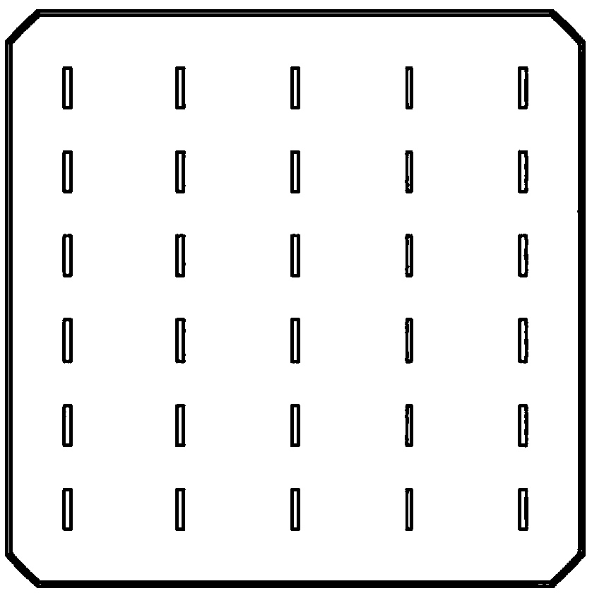
[0022] see Figure 1-Figure 2 , a solar battery string structure, including a plurality of battery slices connected in sequence to form a battery string, and the battery slices include a battery slice main body 8, a bus grid line 1, a main grid line 2, and an auxiliary grid line 3; both sides of the battery slice main body 8 are provided with Bus grid lines 1, main grid lines 2 and auxiliary grid lines 3; several main grid lines 2 and several auxiliary grid lines 3 are arranged on the surface of the cell main body 8 in a staggered connection; the bus grid lines 1 are along the edge of one end of the battery sheet main body set, and the bus bar 1 is connected to the main bar 2.

[0023] The battery slices are connected by welding ribbon 5 to form a battery string; the bus grid line 1 on the lower surface of the previous battery slice in the battery string is connected to the bus...


PUM


Abstract

The invention provides a solar cell string structure comprising multiple cells which are connected in turn to form a cell string. Each cell comprises a cell body, convergence grid lines, primary gridlines and secondary grid lines. The two surfaces of the cell body are provided with the convergence grid lines, the primary grid lines and the secondary grid lines. Multiple primary grid lines and multiple secondary grid lines are connected on the surfaces of the cell body in a staggered way. The convergence grid lines are arranged along the edge of one end of the cell body, and the convergence grid lines are connected with the primary grid lines. According to the structure, the solder band usage in the cell string formation process can be effectively reduced, the series resistance of the component can be reduced and the cost can be reduced.

Description

technical field [0001] The invention belongs to the field of solar cell structures, in particular to a solar cell string structure. Background technique [0002] The conventional graphic design of crystalline silicon solar cells usually adopts four, five or more main grid lines parallel to the edge of the battery sheet, and several auxiliary grid lines extend outward from the main grid lines. The function of the auxiliary grid lines is to collect current. The main function of the main grid line is to collect current and connect to the next battery sheet through soldering. image 3 shown. use image 3 The cells shown are used to make solar photovoltaic modules, and the connection between the cells is formed by welding ribbons on the main grid lines to form battery strings, and the battery strings are connected in parallel through bus bars to form a complete solar photovoltaic module. There are two problems in the use of a large number of ribbons and bus bars. First, the ribb...

Claims


Application Information

Patent Timeline
Patent Type & Authority Applications(China)
IPC IPC(8): H01L31/05H01L31/0224
CPCH01L31/022433H01L31/0508Y02E10/50
Inventor 赵珍陈国清朱琛吕俊王建波王海庆
Owner LONGI SOLAR TECH (TAIZHOU) CO LTD
Learn More