Rotor and permanent magnet motor

A technology for rotors and rotor cores, applied in magnetic circuits, electrical components, electromechanical devices, etc., can solve the problems of unfavorable maximum utilization of magnetic steel and high cost, and achieve the effects of reduced thickness, reduced magnetic flux leakage, and improved torque

Pending Publication Date: 2018-10-26
SUZHOU INOSA UNITED POWER SYST CO LTD
View PDF21 Cites 6 Cited by
  • Summary
  • Abstract
  • Description
  • Claims
  • Application Information

AI Technical Summary

Problems solved by technology

[0006] The technical problem to be solved by the present invention is to provide a rotor and a permanent magnet motor for the above-mentioned pr...

Method used


Image

  • Rotor and permanent magnet motor
  • Rotor and permanent magnet motor
  • Rotor and permanent magnet motor

Examples


Embodiment Construction

[0039] In order to make the object, technical solution and advantages of the present invention clearer, the present invention will be further described in detail below in conjunction with the accompanying drawings and embodiments. It should be understood that the specific embodiments described here are only used to explain the present invention, not to limit the present invention.

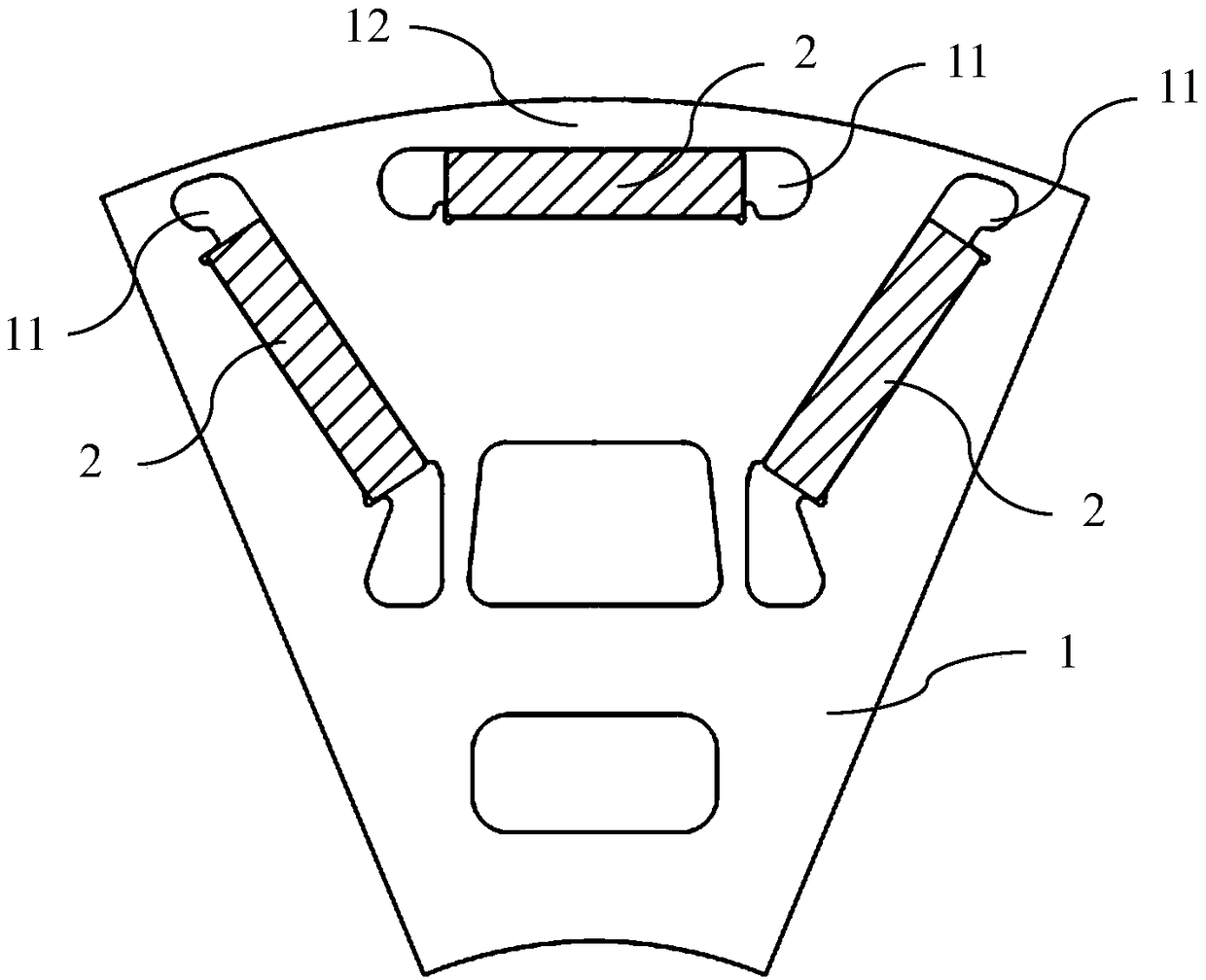
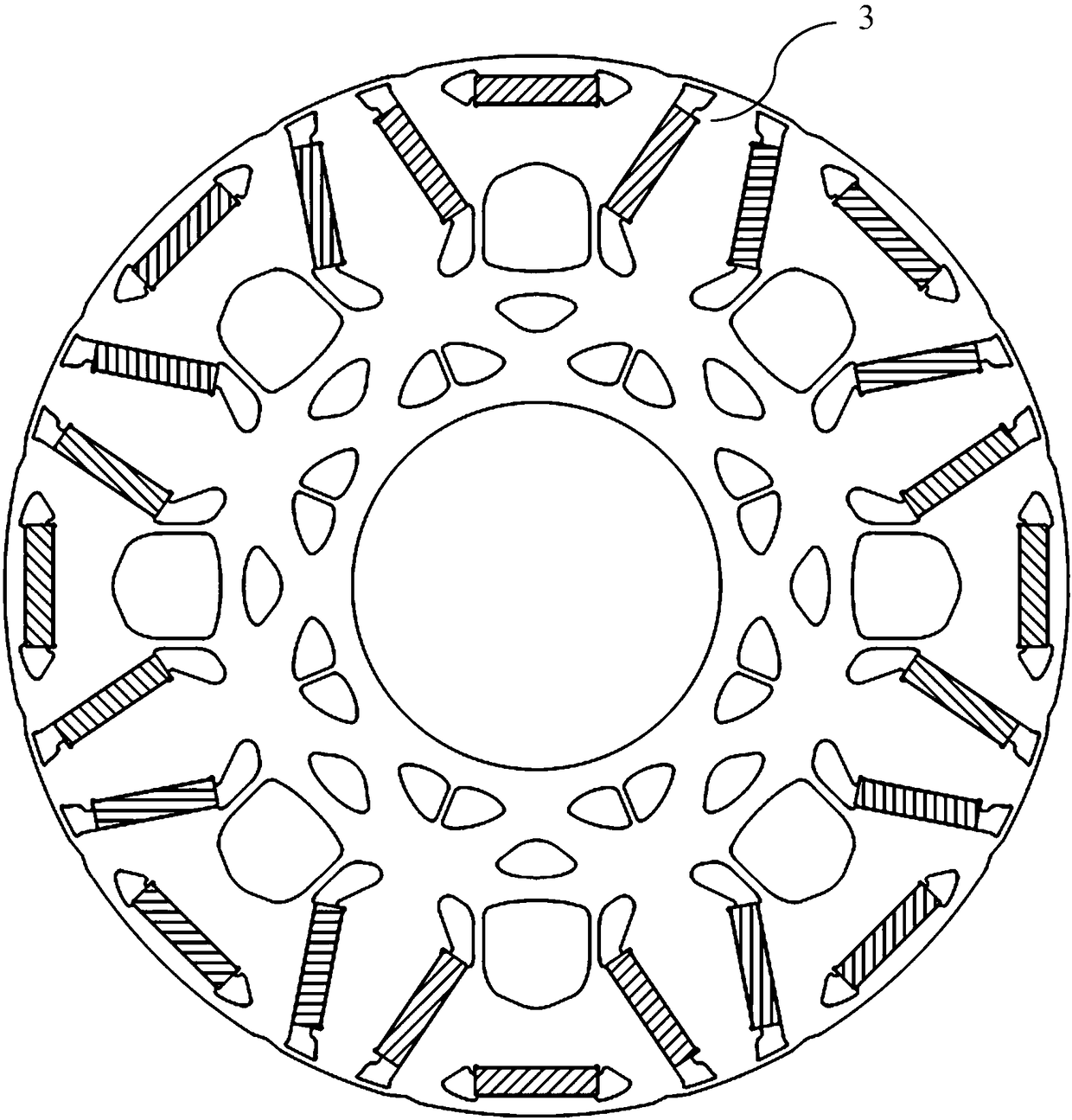
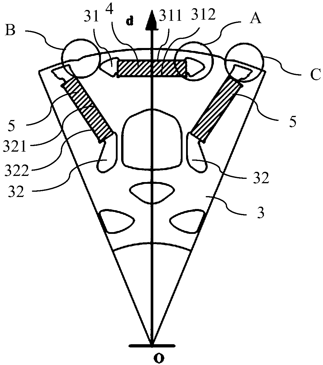
[0040] Such as Figure 2~3Shown is a schematic diagram of an embodiment of the rotor of the present invention, and the rotor can be applied to a permanent magnet motor. The rotor in this embodiment includes a rotor core 3 (the rotor core 3 can be formed by stamping silicon steel sheets), the rotor core 3 includes a plurality of circumferentially distributed magnetic poles, and each magnetic pole includes a A first magnetic steel groove 31 of a magnetic steel (I-type magnetic steel) 4 . The first magnetic steel slots 31 are distributed axisymmetrically with the centerline Od as the axis of symmetr...


PUM

PropertyMeasurementUnit
Radiusaaaaaaaaaa

Abstract

The invention provides a rotor and a permanent magnet motor. The rotor comprises a rotor core, the rotor core comprises a plurality of magnetic poles distributed on the circumferential direction, andeach magnetic pole comprises a first magnetic steel slot; the first magnetic steel slot adopts a center line as a symmetric axis, and the center line is distributed along the radial direction of the rotor core; the first magnetic steel slot comprises an outer wall surface, an inner wall surface and two side wall surfaces, wherein the outer wall surface and the inner wall surfaces are respectivelyplanes and are respectively vertical to the center line; the two side wall surfaces are respectively located at two ends of the first magnetic steel slot and are respectively connected with the outerwall surface and the inner wall surface; each side wall surface is provided with a peak-shaped projection that protrudes toward the outer circumferential surface of the rotor core, and the end part ofthe first magnetic steel slot is located on the inner side of the peak-shaped projection. According to the rotor provided by the invention, the peak-shaped projections are added on the two ends of the first magnetic steel slot to reduce the mechanical stress on the two ends of the first magnetic steel slot during the high-speed running of the rotor while reducing the magnetic flux leakage of therotor core.

Description

technical field [0001] The invention relates to the field of motors, more specifically, to a rotor and a permanent magnet motor. Background technique [0002] Environmental pollution and energy crisis have promoted the vigorous development of the new energy vehicle industry, especially the electric vehicle industry. As one of the key executive components of electric vehicles, the performance of vehicle drive motors is crucial to the performance of the entire vehicle. Due to the advantages of high power density and high efficiency, permanent magnet motors have been widely used in the field of vehicle drive motors. In order to increase the power density of the drive system, a combination of permanent magnet motor and reducer is usually used to provide driving force for electric vehicles. [0003] Due to the special operating conditions of electric vehicles, permanent magnet motors are usually required to have higher power density, so the maximum speed of the motor is usually ...

Claims


Application Information

Patent Timeline
IPC IPC(8): H02K1/27
CPCH02K1/2766H02K2213/03
Inventor 杨深蒋奎褚文强李寰纹张杰章正昌李庆旭蔡瑞环
Owner SUZHOU INOSA UNITED POWER SYST CO LTD
Why Eureka
Try Eureka