Automatic calibration method for line structured light visual system of arc welding robot

A vision system, line structured light technology, applied in instruments, manipulators, welding accessories, etc., can solve the problems of time-consuming and complex calibration process, achieve good practicability, improve flexibility and rapidity, and the calibration process is simple and convenient Effect

Active Publication Date: 2018-10-30
SOUTH CHINA UNIV OF TECH +1
View PDF12 Cites 39 Cited by
  • Summary
  • Abstract
  • Description
  • Claims
  • Application Information

AI Technical Summary

Problems solved by technology

[0004] Aiming at the disadvantages of relying on human operation, complex calibration process, and time-consuming calibration process in the existing calibratio

Method used


Image

  • Automatic calibration method for line structured light visual system of arc welding robot
  • Automatic calibration method for line structured light visual system of arc welding robot
  • Automatic calibration method for line structured light visual system of arc welding robot

Examples


Embodiment Construction

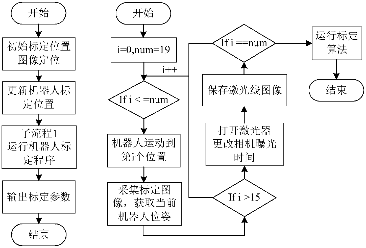
[0052] In order to make the purpose, technical solution and advantages of the present invention clearer, the specific implementation process of the present invention will be further described in detail below with reference to the accompanying drawings.

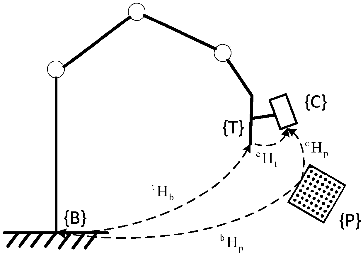
[0053] The calibration relationship of the coordinate system of the arc welding robot structured light vision system: figure 1 shown. The structured light vision sensor is fixed on the welding torch of the arc welding robot, and the calibration plate is located in the working space of the robot. {B} is the robot base coordinate system, {C} is the visual sensor coordinate system, that is, the camera coordinate system, {T} is the robot tool coordinate system, that is, the welding torch coordinate system, and {P} is the calibration plate coordinate system. According to the matrix transfer relationship, we can get

[0054] c h p = c h t t h b b h p

[0055] in, c h p is the transformation matrix from the calibration p...


PUM


Abstract

The invention discloses an automatic calibration method for a line structured optical visual system of an arc welding robot. The method comprises the steps of: 1, placing a calibration plate at any position in a working area of the robot according to a predetermined constraint limit; 2, manually manipulating the robot to ensure that the position of the calibration plate is in a rectangular frame in the middle of a collected image and updating the position component of each collection point in a robot calibration program on the basis; 3, collecting 15 calibration plate images in 15 positions and calibration plate images in other 4 positions and the corresponding laser stripe images; and 4, calculating internal parameters of a camera and hand-eye relationship parameters through the collectedprevious 15 images and calculating structured light plane parameters through the collected latter four images. The method disclosed by the invention has the advantages that image positioning is onlycarried out on the first collection position of the calibration plate and the subsequent positions are automatically updated through translation transformation with no need for human operation, so that the calibration method is convenient and quick, the flexibility and the rapidity are greatly increased and the method can meet the needs of actual production environments.

Description

technical field [0001] The invention relates to a line structured light vision system of an arc welding robot, in particular to an automatic calibration method for the line structured light vision system of an arc welding robot. Background technique [0002] Due to its non-contact characteristics, the line structured light vision sensor has high measurement accuracy and fast measurement speed, and is more widely used in industrial applications than contact sensing methods. In the application of seam tracking, the line structured light vision sensor is usually fixed on the welding torch of the robot to detect and automatically track the seam. [0003] The method of fixing the line-structured light vision sensor on the end of the arc welding robot is the eye in hand mode. The sensor moves with the robot. In order to unify the position detected by the sensor to the robot base coordinate system, it is necessary to carry out three steps on the vision system of the arc welding rob...

Claims


Application Information

Patent Timeline
IPC IPC(8): G06T7/80B23K9/32B25J19/00
CPCG06T7/80B23K9/32B25J19/00
Inventor 王念峰石小东
Owner SOUTH CHINA UNIV OF TECH
Why Eureka
Try Eureka