Supercharge Your Innovation With Domain-Expert AI Agents!

A Method for Improving the Bottom Scouring of Vacuum Induction Melting Ingot Mold

A technology of vacuum induction smelting and steel ingot mould, which is applied in ingot workshops, casting molten material containers, process efficiency improvement, etc., can solve problems such as high cost, deterioration of steel ingot purity, and difficult supply, and achieve the goal of prolonging service life Effect

Active Publication Date: 2020-10-16
JIANGSU JICUI ADVANCED METAL MATERIAL RES INST CO LTD
View PDF9 Cites 0 Cited by
  • Summary
  • Abstract
  • Description
  • Claims
  • Application Information

AI Technical Summary

Problems solved by technology

These two methods improve the life of the chassis, but the use of refractory materials will lead to deterioration of the purity of the steel ingot, and the same type of steel bottom plate is difficult to supply, and the cost is high

Method used


Image

  • A Method for Improving the Bottom Scouring of Vacuum Induction Melting Ingot Mold
  • A Method for Improving the Bottom Scouring of Vacuum Induction Melting Ingot Mold
  • A Method for Improving the Bottom Scouring of Vacuum Induction Melting Ingot Mold

Examples


Embodiment 1

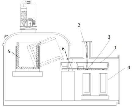
[0014] refer to figure 1 , 2 And 3, vacuum induction melting and casting of superalloy GH4169, including the following steps:

[0015] Step 1: Use gas or natural gas to bake the L-shaped tundish, put the baked L-shaped tundish 1 into the casting chamber, and start vacuuming, turn on the heating switch of the L-shaped tundish 1 to start heating. After the vacuum degree of the casting chamber is the same as that of the melting chamber, the vacuum isolation valve 6 is opened, and the L-shaped tundish 1 is moved to the pouring position. Lower the stopper device 2 to the gate. The maximum superheat of the molten pool is controlled at Tm+30°C.

[0016] Step 2: Tilt the crucible 1 to start pouring. When the solution in the L-shaped tundish 1 reaches two-thirds of the height, lift the stopper rod by 3mm, so that the high-temperature GH4169 melt flows into the spiral nozzle 3 at a low flow rate and low flow rate, and passes through the spiral nozzle. The nozzle 3 changes the vertic...

Embodiment 2

[0018] refer to figure 1 , 2 And 3, vacuum induction melting and casting of superalloy GH4169, including the following steps:

[0019] Step 1: Use gas or natural gas to bake the L-shaped tundish, put the baked L-shaped tundish 1 into the casting chamber, and start vacuuming, turn on the heating switch of the L-shaped tundish 1 to start heating. After the vacuum degree of the casting chamber is the same as that of the melting chamber, the vacuum isolation valve 6 is opened, and the L-shaped tundish 1 is moved to the pouring position. Lower the stopper device 2 to the gate. The maximum superheat of the molten pool is controlled at Tm+50°C.

[0020] Step 2: Tilt the crucible 1 to start pouring. When the solution in the L-shaped tundish 1 reaches two-thirds of the height, lift the stopper rod by 5mm, so that the high-temperature GH4169 melt flows into the spiral nozzle 3 at a low flow rate and low flow rate, and passes through the spiral nozzle. The nozzle 3 changes the vertic...


PUM


Abstract

The invention discloses a device and a method for relieving the bottom scour of a vacuum induction smelting ingot mold which includes a smelting chamber and a casting chamber. A vacuum isolating valveis arranged between the smelting chamber and the casting chamber, a crucible is arranged in the smelting chamber, and a heatable L-shaped tundish is arranged in the casting chamber which is used forreducing the degree of superheat in casting. A stopper rod device is arranged on the upper portion of the L-shaped tundish, the upper end of the stopper rod device is connected with the top of the casting chamber, and a telescopic stopper rod is arrange on the lower end of the stopper rod device. The stopper rod device is used for controlling the casting speed and the amount of molten solution atthe initial stage. A spiral water gap is formed in the bottom of the L-shaped tundish, and the spiral water gap is used for slowing down the flow down rate of the high-temperature melt and a dispersion flow is formed so as to expand the area of the melt falling to the bottom of the ingot mold. According to the device and the method for the relieving bottom scour of the vacuum induction smelting ingot mold, the problem that the bottom of the ingot mold is scoured seriously can be effectively solved, and the service life of a base plate can be effectively prolonged.

Description

technical field [0001] The invention belongs to the field of special metallurgy and relates to a vacuum metallurgical process of high-performance metal materials, in particular to a method for improving the scour at the bottom of a steel ingot mold for vacuum induction melting. Background technique [0002] High-performance alloys need to be poured into ingot molds to form steel ingots or electrodes after vacuum induction smelting. The pouring process is to direct high-temperature melt from the crucible into the ingot mold, or pass through the tundish and flow out from the nozzle into the ingot mold. In the above process , due to the high temperature of the melt and the large flow rate, the bottom of the ingot mold is severely scoured. First, the life of the chassis is severely shortened, and second, the control of the high-performance alloy composition is likely to be affected to a certain extent. [0003] In current industrial practice, in order to improve the erosion of t...

Claims


Application Information

Patent Timeline
Patent Type & Authority Patents(China)
IPC IPC(8): B22D41/50B22D41/16C22B9/04B22D9/00
CPCB22D9/00B22D41/16B22D41/507C22B9/04Y02P10/25
Inventor 沈海军张丕军王建伟程兴德王国栋
Owner JIANGSU JICUI ADVANCED METAL MATERIAL RES INST CO LTD
Features
  • R&D
  • Intellectual Property
  • Life Sciences
  • Materials
  • Tech Scout
  • Unparalleled Data Quality
  • Higher Quality Content
  • 60% Fewer Hallucinations
Learn More