
Guide rail type cutting machine

A cutting machine and rail-type technology, which is applied in metal processing and other directions, can solve the problems of reducing work efficiency, time-consuming, and labor-intensive operators, so as to save time, avoid cutting errors, and reduce labor intensity.

Pending Publication Date: 2018-11-02
江苏华驰机械有限公司
View PDF8 Cites 1 Cited by
  • Summary
  • Abstract
  • Description
  • Claims
  • Application Information

AI Technical Summary

Problems solved by technology

[0003] The cutting head of most cutting machines on the market can only be lifted up and down above the workbench. Therefore, when it is necessary to cut the different positions of the material, the material can only be moved. Every time the material is moved, it needs to be adjusted. The position of the material to ensure the accuracy of cutting, which not only takes a lot of time and reduces work efficiency, but also the labor intensity of the operator is relatively high

Method used


Image

  • Guide rail type cutting machine
  • Guide rail type cutting machine
  • Guide rail type cutting machine

Examples


Embodiment Construction

[0019] The present invention will be further explained below in conjunction with the accompanying drawings and specific embodiments. It should be understood that the following specific embodiments are only used to illustrate the present invention and are not intended to limit the scope of the present invention. It should be noted that the words "front", "rear", "left", "right", "upper" and "lower" used in the following description refer to the directions in the drawings, and the words "inner" and "outer ” refer to directions towards or away from the geometric center of a particular part, respectively.

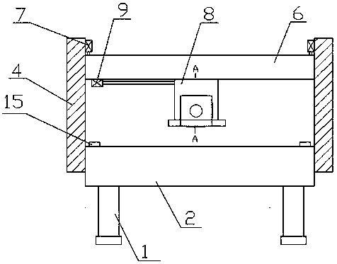
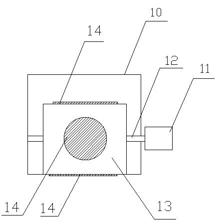
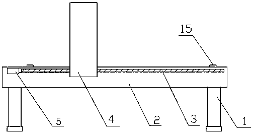
[0020] As shown in the figure, a rail-type cutting machine according to the present invention includes a frame 1 and a controller. The frame 1 is fixed with a workbench 2, and both sides of the workbench 2 are provided with horizontal The guide rails 3 in the direction, the guide rails 3 are all slidably provided with uprights 4, and the uprights 4 are all connected with the dr...


PUM


Abstract

The invention discloses a guide rail type cutting machine which comprises a rack and a controller. A worktable is fixedly arranged on the rack; guide rails in horizontal direction are arranged on twosides of the worktable; columns are slidably arranged on the guide rails; the columns are in transmission connection to a driving device I; vertical chutes are formed in opposite side faces of the twocolumns; an upper pressure plate is arranged between the two columns; the upper pressure plate is slidably arranged between the columns through the chutes; the upper pressure plate is in transmissionconnection to a driving device II; a sliding track is arranged on the lower end surface of the upper pressure plate; a cutting head is slidably arranged on the sliding track; the cutting head is in transmission connection to a driving device III; and the driving devices I, II and III are electrically connected to the controller. The guide rail type cutting machine disclosed by the invention is novel in structure. The position of the cutting head can be adjusted, so that any positions of a material on the worktable can be cut. The material needs not to be moved frequently, so that the work efficiency is improved effectively.

Description

technical field [0001] The invention relates to the technical field of cutting machine equipment, in particular to a guide rail type cutting machine. Background technique [0002] As an important equipment in the footwear industry, luggage industry and clothing industry, the cutting machine is the key to realize the automation of production in related industries, improve production efficiency and ensure product quality. It is also an important manifestation of the technical level and competitiveness of enterprises. Therefore, it is widely used in Processing of foamed materials, cardboard, textiles, plastic materials, rubber, packaging materials, flooring materials, carpets, fiberglass, cork and other materials. [0003] The cutting head of most cutting machines on the market can only be lifted up and down above the workbench. Therefore, when it is necessary to cut the different positions of the material, the material can only be moved. Every time the material is moved, it ne...

Claims


Application Information

Patent Timeline
Patent Type & Authority Applications(China)
IPC IPC(8): B26F1/44B26D7/26
CPCB26D7/2614B26D7/2628B26F1/44
Inventor 刘传堂
Owner 江苏华驰机械有限公司
Learn More