Ceramic forming mold automatic exchange machine

A technology for molding molds and changing machines, which is applied in ceramic molding machines, auxiliary molding equipment, conveyors, etc., can solve the problems of low production efficiency and high production costs, and achieve the advantages of small equipment footprint, high degree of automation, and precise positioning Effect

Inactive Publication Date: 2018-11-02
福建省德化博龙陶瓷有限公司
View PDF0 Cites 4 Cited by
  • Summary
  • Abstract
  • Description
  • Claims
  • Application Information

AI Technical Summary

Problems solved by technology

[0002] Ceramics are common daily necessities in people's daily life. The production of ceramics goes through processes such as body forming, glazing, and firing. The body forming includes steps such as mud configuration, mud refining, feeding, forming, drying, and cleaning. The above-mentioned steps in the traditional ceramic forming process are all manually operated, but with the advent of industrialization, a large number of automated equipment are used in modern ceramic forming production, including automatic mud refining machine, mud bar fixed-length cutting machine, automatic forming machine, automatic baking machine, etc. Drying machines, etc., but in the connecting link of some equipment, manual work is still required. For example, the plaster model with built-in mud needs to be manually transported from the production line to the automatic forming machine, and then manually transported back to the conveyor line after forming In fact, not only the production efficiency is low, but also the production cost is high. With the continuous increase of labor costs, the traditional ceramic molding production line obviously cannot meet the needs of modern lean and automated production

Method used


Image

  • Ceramic forming mold automatic exchange machine
  • Ceramic forming mold automatic exchange machine
  • Ceramic forming mold automatic exchange machine

Examples


Embodiment Construction

[0016] The present invention will be further described below through specific embodiments.

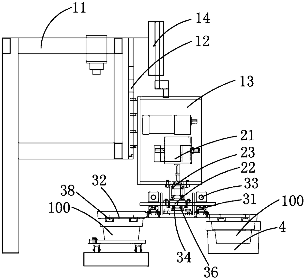
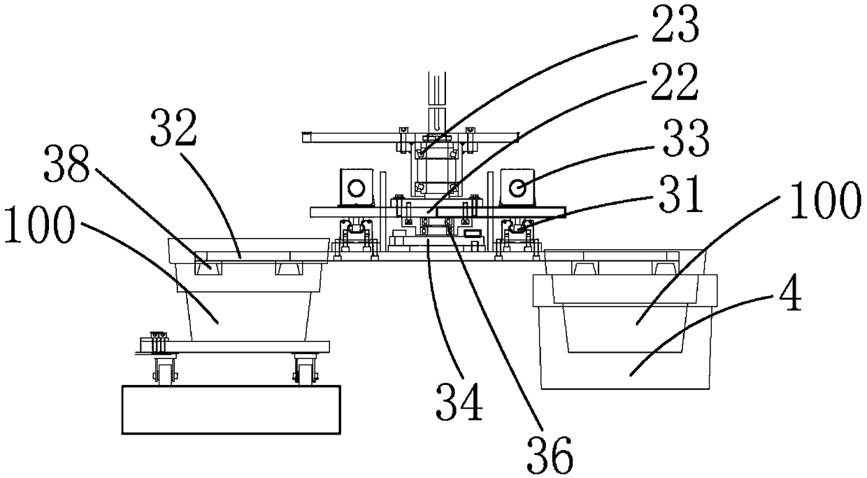
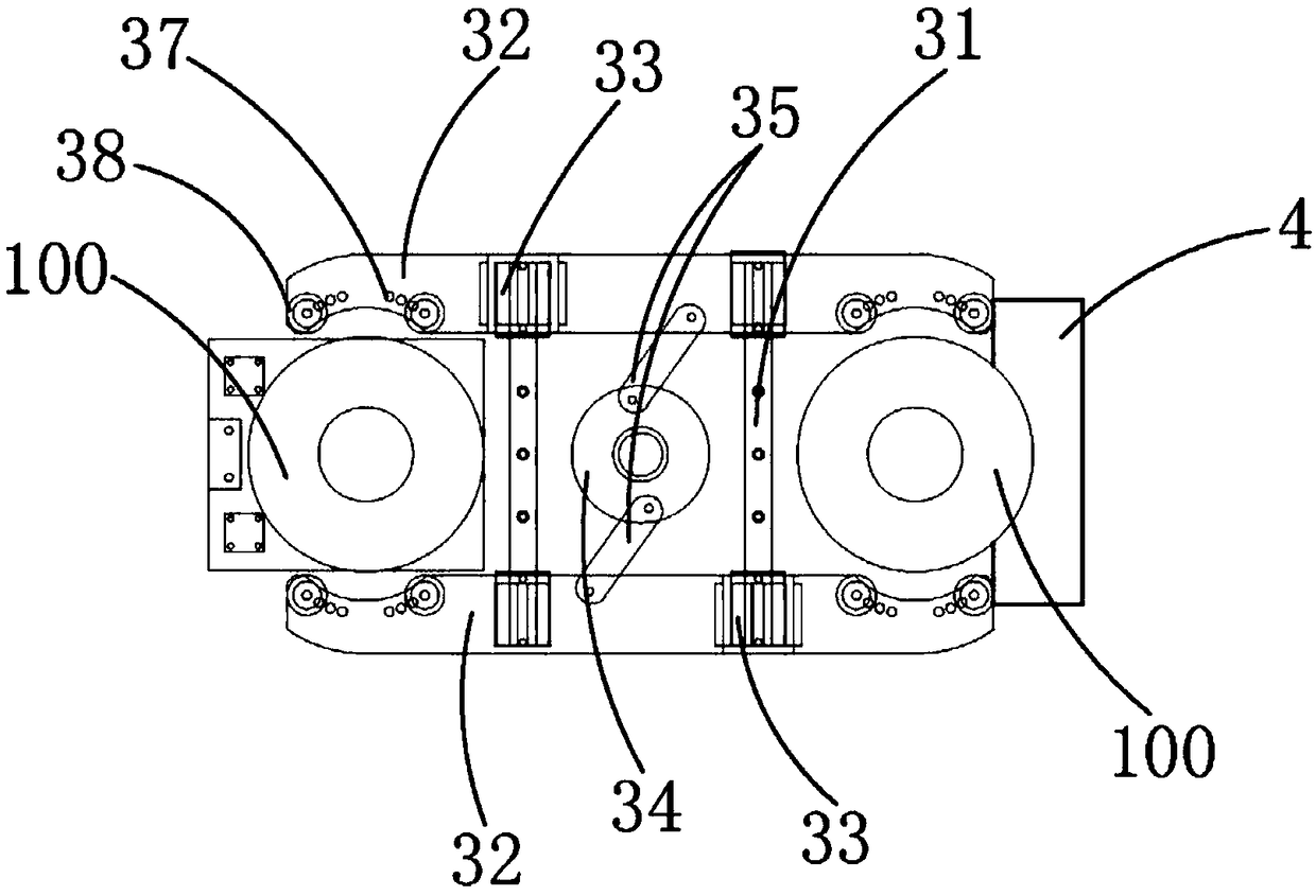
[0017] As shown in the figure, the automatic exchange machine for ceramic forming molds of the present invention includes a longitudinal movement mechanism, an exchange mechanism and a clamping mechanism.

[0018] Such as figure 1 As shown, the longitudinal moving mechanism includes a mold clamping frame 11, a longitudinal slide rail 12 fixed on the clamping mold frame 11, a longitudinal moving frame 13 slidingly arranged on the longitudinal sliding rail 12, and a longitudinal moving frame for driving the longitudinal moving frame 13 to move. The driving unit 14, the longitudinal driving unit 14 drives the longitudinal moving frame 13 and the clamping mechanism to move up and down along the longitudinal direction, and the longitudinal driving unit 14 can be an electric screw slide table.

[0019] The exchange mechanism includes an exchange servomotor 21 fixed on the longitudinal movin...


PUM


Abstract

The invention relates to the field of ceramic forming production equipment, in particular to a ceramic forming mold automatic exchange machine. The ceramic forming mold automatic exchange machine is characterized by comprising a longitudinal moving mechanism, an exchange mechanism and a clamping mechanism; the longitudinal moving mechanism comprises a mold clamping rack, a longitudinal slide railfixedly arranged on the mold clamping rack, a longitudinal moving rack slidably arranged on the longitudinal slide rail and a longitudinal driving unit driving the longitudinal moving rack to move; the exchange mechanism comprises an exchange servo motor fixedly arranged on the longitudinal moving rack and a rotary frame driven by the exchange servo motor to rotate. According to the ceramic forming mold automatic exchange machine provided by the invention, rising, dropping, position exchange and clamping of plaster molds can be implemented through the longitudinal moving mechanism, the exchange mechanism and the clamping mechanism; unformed plaster molds on a production line and formed plaster mold on an automatic forming machine can be exchanged; the automation degree is high, manual carrying of molds is omitted; the production efficiency is improved; and the labor cost is lowered.

Description

technical field [0001] The invention relates to the field of ceramic molding production equipment, in particular to an automatic exchange machine for ceramic molding molds. Background technique [0002] Ceramics are common daily necessities in people's daily life. The production of ceramics goes through processes such as body forming, glazing, and firing. The body forming includes steps such as mud configuration, mud refining, feeding, forming, drying, and cleaning. The above-mentioned steps in the traditional ceramic forming process are all manually operated, but with the advent of industrialization, a large number of automated equipment are used in modern ceramic forming production, including automatic mud refining machine, mud bar fixed-length cutting machine, automatic forming machine, automatic baking machine, etc. Drying machines, etc., but in the connecting link of some equipment, manual work is still required. For example, the plaster model with built-in mud needs to...

Claims


Application Information

Patent Timeline
IPC IPC(8): B28B17/00B65G47/90
CPCB28B17/00B65G47/902B65G47/907B65G2201/0235
Inventor 张金涵李小阳
Owner 福建省德化博龙陶瓷有限公司
Why Eureka
Try Eureka