Eureka AIR delivers breakthrough ideas for toughest innovation challenges, trusted by R&D personnel around the world.

Packaging process for gear

A packaging technology and gear technology, which is applied in the field of gear processing, can solve the problems of affecting gear processing efficiency, gear production efficiency, and adhesion on gears, so as to improve speed and precision, prevent slipping, and avoid damage.

Inactive Publication Date: 2018-11-02
重庆聚伯雅科技有限公司
View PDF3 Cites 0 Cited by
  • Summary
  • Abstract
  • Description
  • Claims
  • Application Information

AI Technical Summary

Problems solved by technology

[0003] After the seventh step of gear processing is completed, the gears are generally cleaned, packaged or assembled in sequence. The purpose of cleaning is to remove the waste on the surface of the gear and prevent the waste from adhering to the gear; the packaging is for convenience. To protect the gears and keep the gears in a non-destructive state, these two operations are generally carried out separately, which has an impact on the production efficiency of the gears; at the same time, when cleaning the gear surface, manual cleaning is generally used to clean up the waste debris. During the process, it is difficult to quickly and effectively clean the waste chips adhered to the tooth root, which will further affect the processing efficiency of the gear

Method used


Image

  • Packaging process for gear
  • Packaging process for gear
  • Packaging process for gear

Examples


Embodiment Construction

[0022] Further detailed explanation through specific implementation mode below:

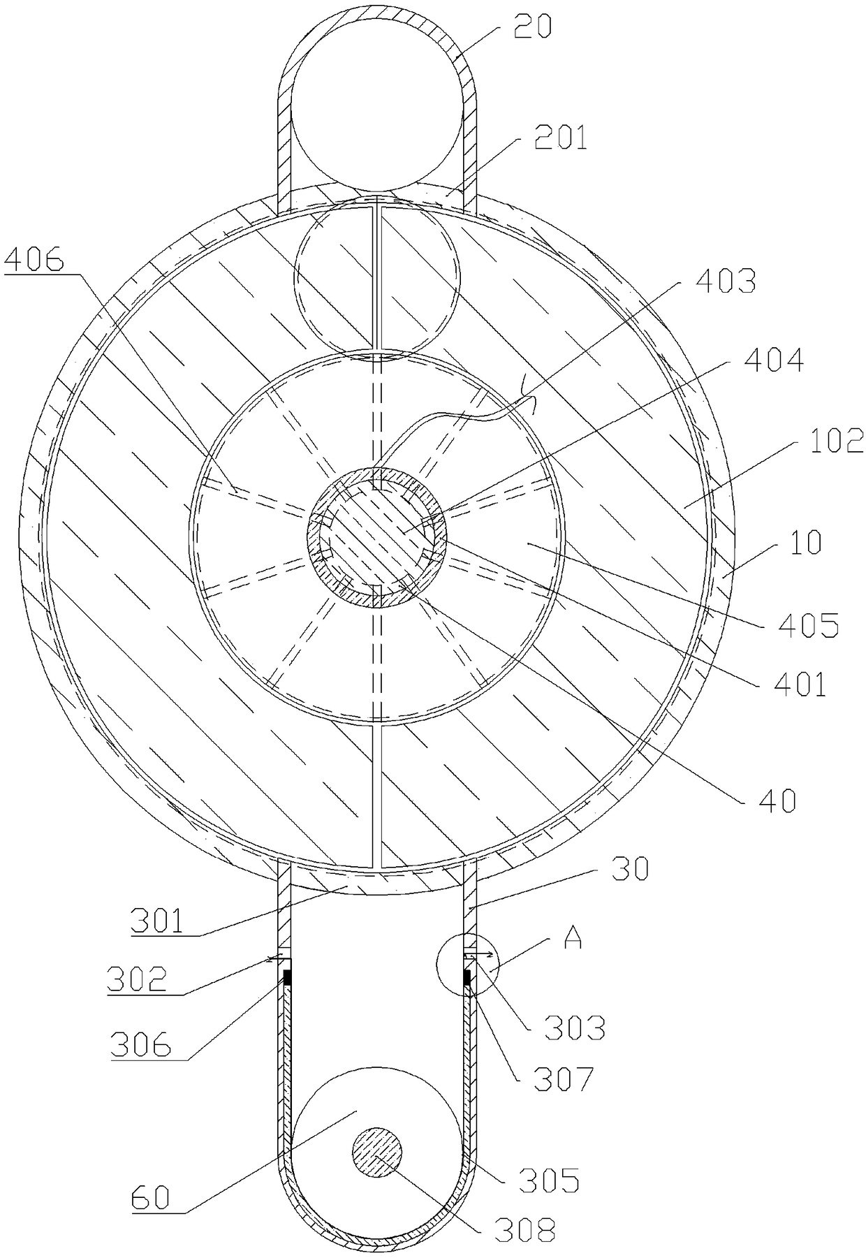
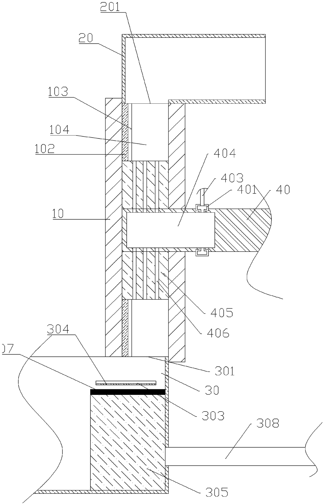
[0023] The reference numerals in the accompanying drawings of the description include: delivery box 10, cleaning cotton 102, installation port 103, delivery cavity 104, second delivery cylinder 20, discharge port 201, first delivery cylinder 30, feed inlet 301, first Through hole 302, second through hole 303, sawtooth 304, buffer plate 305, first electromagnet 306, second electromagnet 307, push rod 308, rotating shaft 40, fixing ring 401, air intake pipe 403, air intake cavity 404, transmission Wheel 405, runner 406, air outlet 407, packing material 50, gear 60.

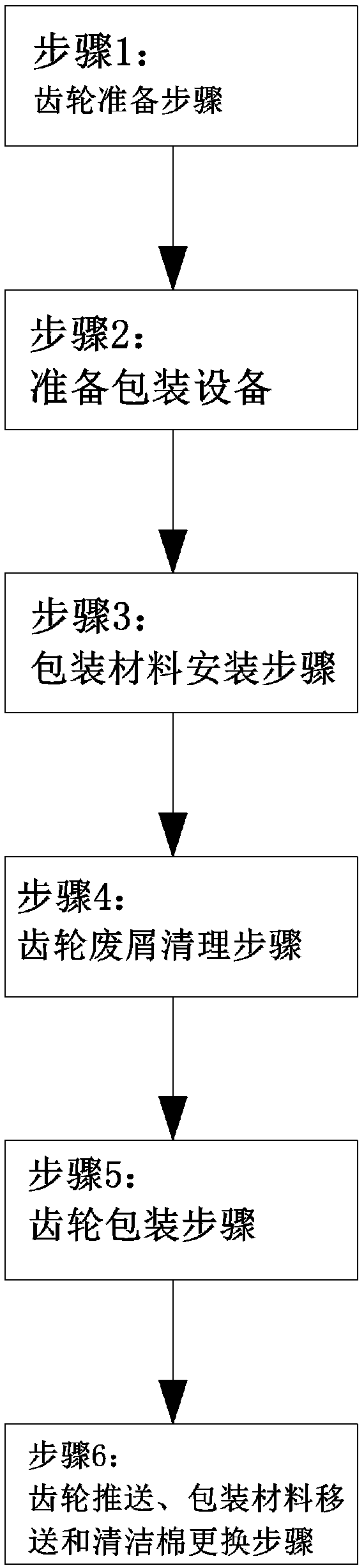
[0024] The operating steps of the packaging process for gears in the present embodiment are basically as attached figure 1 As shown, the specific steps are as follows:

[0025] Step 1: Prepare packing materials and several gears to be packed.

[0026] Step 2: Prepare a basic as attached figure 2 , attached image 3 , attached F...


PUM


Abstract

The invention relates to the field of gear machining and particularly discloses a packaging process for a gear. The packaging process comprises the steps of preparation of packaging materials and thegear, installation of the packaging materials, conveying of the gear and moving of the packaging materials, and gear packaging. According to the step of preparation of the packaging materials and thegear, packaging equipment is prepared and comprises a first conveying barrel and a packaging mechanism, the upper surface of the first conveying barrel is provided with a feed inlet, and the gear canvertically falls through the feed inlet; the packaging mechanism comprises an elastic buffer plate, a first electromagnet and a second electromagnet; the lower surface of the first conveying barrel isan outwards convex cambered surface; the bottom face of the first conveying barrel is provided with an installing groove for installing a buffer plate; the upper surface of the buffer plate is opposite to the feed inlet; the first electromagnet is fixedly installed on one side of the buffer plate; the second electromagnet is fixedly installed on the other side of the buffer plate, and the first electromagnet and the second electromagnet are each provided with an electric heating wire for hot melting of the packaging materials. Through the packaging process, gear machining efficiency can be improved.

Description

technical field [0001] The invention belongs to the field of gear processing, and in particular relates to a packaging process for gears. Background technique [0002] A gear is a mechanical element with gears on the rim that continuously meshes to transmit motion and power. It is also the most commonly eaten mechanical component in common mechanical equipment. It has the functions of power transmission, speed change and reversing. The processing of gears generally has the following 7 processing steps, which are in order: 1. According to different requirements, casting and forging methods are used to make gear blanks; 2. Heat treatment; 3. Gear blank turning; 4. Gear hobbing or gear shaping; 5. 6. Tooth surface heat treatment; 7. Grinding or grinding teeth. [0003] After the seventh step of gear processing is completed, the gears are generally cleaned, packaged or assembled in sequence. The purpose of cleaning is to remove the waste on the surface of the gear and prevent t...

Claims


Application Information

Patent Timeline
IPC IPC(8): B65B63/00B65B35/42B65B51/10B65B61/10
CPCB65B35/42B65B51/10B65B61/10B65B63/00
Inventor 张小恒詹华山李涛黄诗鸿曾雨琳袁苗达
Owner 重庆聚伯雅科技有限公司
Why Eureka
Eureka Blog
Learn More