Sensor encapsulation structure and method

A packaging structure and packaging method technology, applied in microstructure technology, microstructure devices, manufacturing microstructure devices, etc., can solve the problems of increasing dams, incompetent for automotive-grade safety-related applications, weak reliability, etc., and reduce packaging. Cost and packaging difficulty, the effect of shortening production and manufacturing cycle, and reducing packaging cost

Pending Publication Date: 2018-11-02
南京英锐创电子科技有限公司
View PDF0 Cites 8 Cited by
  • Summary
  • Abstract
  • Description
  • Claims
  • Application Information

AI Technical Summary

Problems solved by technology

The manufacturing process of the above-mentioned first method is relatively simple, but because all chips and bonding wires are protected by soft protective glue, the reliability is relatively weak, especially for those complex packages, such as multi-chip packaging, or multiple bonding wires Packaging, it is difficult to meet the requirements of high reliability, and it is not suitable for automotive-level safety-related applications
Although the reliability of the second method mentioned above is improved compared with the prefabricated frame solution, the process is relatively complicated, and the process control requirements for packaging are also higher than the first method. For example, the process of enclosing the dam needs to be added.

Method used


Image

  • Sensor encapsulation structure and method
  • Sensor encapsulation structure and method
  • Sensor encapsulation structure and method

Examples


Embodiment 1

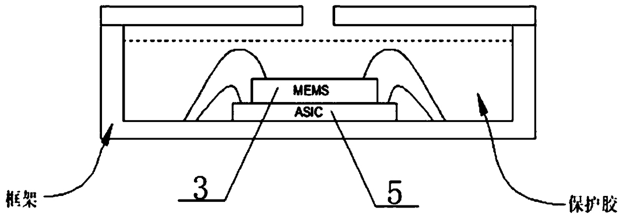
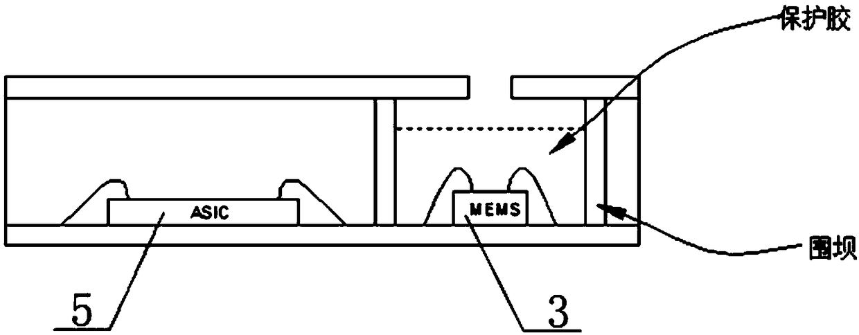
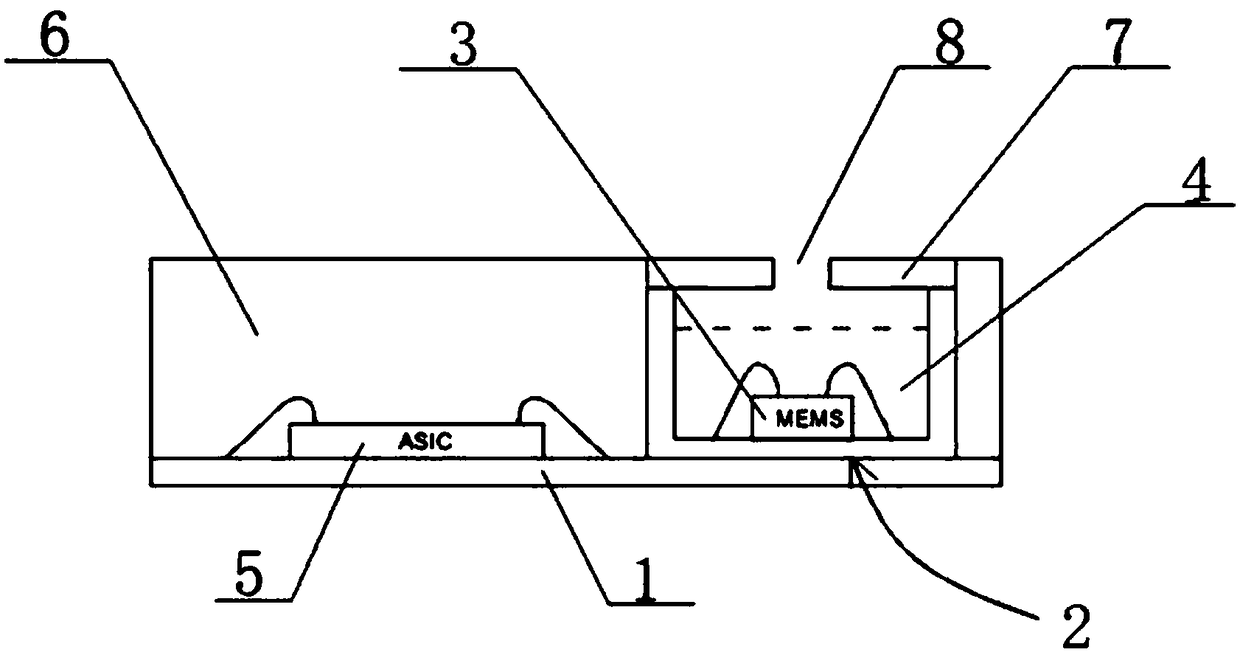
[0055] image 3 It is a schematic structural diagram of the sensor package structure provided by the embodiment of the present invention under a viewing angle, Figure 4 For a structural schematic diagram of the first package body of the sensor package structure provided by the embodiment of the present invention under a viewing angle, please refer to image 3 , 4 As shown, the sensor packaging structure of this embodiment includes a circuit substrate 1, a prefabricated substrate 2, a MEMS pressure sensor 3, a first colloid 4, an ASIC chip 5, and a second colloid 6; the prefabricated substrate 2 includes a bottom plate 21 and the The side wall 22 connected to the base plate 21, the base plate 21 and the side wall 22 surround a cavity 23 with an upper end opening, the MEMS pressure sensor 3 is arranged in the cavity 23, and the MEMS pressure sensor 3 is electrically connected to the prefabricated substrate 2, and the MEMS pressure sensor 3 is encapsulated in the cavity 23 thr...

Embodiment 2

[0064] Figure 5 Schematic diagram of the sensor packaging structure provided in the embodiment of the present invention during the packaging process Image 6 For the schematic structural diagram of the sensor packaging structure provided in the embodiment of the present invention during the packaging process, please refer to image 3 -6, the present embodiment provides a sensor packaging method, the packaging method includes the following steps:

[0065] Provide a circuit substrate 1 and a prefabricated substrate 2, the prefabricated substrate 2 includes a bottom plate 21 and a side wall 22 connected to the bottom plate 21, the bottom plate 21 and the side wall 22 enclose a cavity 23 with an open upper end ;

[0066] placing the MEMS pressure sensor 3 in the cavity 23, electrically connecting the MEMS pressure sensor 3 to the prefabricated substrate 2, injecting the first colloid 4 into the cavity 23 to form a first package;

[0067] Electrically connecting the ASIC chip 5...


PUM


Abstract

The invention discloses a sensor encapsulation structure and method, and relates to the technical field of sensor encapsulation. The sensor encapsulation structure comprises a line base plate, a prefabricated base plate, MEMS pressure sensors, a first rubber matrix, an ASIC chip and a second rubber matrix. The prefabricated base plate comprises a bottom plate and a side wall connected with the bottom plate. A cavity with the open upper end is defined by the bottom plate and the side wall. The MEMS pressure sensors are arranged in the cavity and electrically connected with the prefabricated base plate. The MEMS pressure sensors are encapsulated in the cavity through the first rubber matrix. The ASIC chip is electrically connected with the line base plate. The bottom plate of the prefabricated base plate is electrically connected with the line base plate. The ASIC chip and the prefabricated base plate are encapsulated on the line base plate through the second rubber matrix. The sensor encapsulation structure is high in reliability, the sensor encapsulation method is low in encapsulation difficulty, and the situation that a special mold is prefabricated in advance is not needed in theencapsulation process of the MEMS pressure sensors, so that the development cost in the early stage is greatly reduced.

Description

technical field [0001] The invention relates to the technical field of sensor packaging, in particular to a sensor packaging structure and method. Background technique [0002] A pressure sensor is a device or device that can sense pressure signals and convert the pressure signals into usable output electrical signals according to certain rules. Microelectromechanical systems (MEMS) sensors use microelectronics and micromachining technologies new sensor produced. Compared with traditional sensors, MEMS sensors have the characteristics of small size, light weight, low cost, low power consumption, high reliability, suitable for mass production, easy integration and intelligentization, making it possible to complete some traditional mechanical Functions that cannot be realized by sensors. [0003] Based on the above characteristics, MEMS pressure sensors have been applied in medical, automotive, and photographic fields, such as tire pressure sensors, fuel pressure sensors, en...

Claims


Application Information

Patent Timeline
Patent Type & Authority Applications(China)
IPC IPC(8): B81B7/00B81B7/02B81C1/00
CPCB81B7/02B81B7/0032B81B2201/0264B81C1/00261
Inventor 陈斌峰李曙光
Owner 南京英锐创电子科技有限公司
Why Eureka
Try Eureka