A high-efficiency treatment equipment for hydraulic engineering sludge
A technology for treatment equipment and water conservancy projects, applied in water/sludge/sewage treatment, sludge treatment, chemical instruments and methods, etc., it can solve the problems of insufficient contact and unsatisfactory treatment effect, and improve efficiency. , the effect of saving the use of resources and reducing the cost
- Summary
- Abstract
- Description
- Claims
- Application Information
AI Technical Summary
Problems solved by technology
Method used
Image
Examples
Embodiment 1
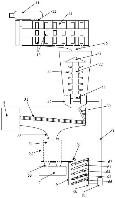
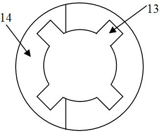
[0028] like figure 1 and figure 2 Shown: a high-efficiency sludge treatment equipment for water conservancy projects, including a crushing chamber, a centrifugal mixing chamber, a stone removal chamber, a separation chamber, a filtering chamber and a recovery water pipe.
[0029] The crushing chamber includes a suction mud pump, a casing of the crushing chamber, a crushing shaft part, an inlet of the crushing chamber and an outlet of the crushing chamber; the suction mud pump is arranged outside the casing of the crushing chamber and is used for sucking the sludge, and a terminal of the suction mud pump is provided with The mud outlet, the mud outlet of the mud suction pump is communicated with the inlet of the crushing chamber, and the inlet of the crushing chamber is arranged on the top of the casing of the crushing chamber. A crushing shaft part is arranged, and the crushing shaft part includes a horizontal crushing shaft, 6 rows of crushing shaft teeth (4 in each row) ar...
Embodiment 2
[0041] The utility model relates to a high-efficiency sludge treatment equipment for water conservancy projects, comprising a crushing chamber, a centrifugal mixing chamber, a stone removing chamber, a separation chamber, a filtering chamber and a recovery water pipe.
[0042] The crushing chamber includes a suction mud pump, a casing of the crushing chamber, a crushing shaft part, an inlet of the crushing chamber and an outlet of the crushing chamber; the suction mud pump is arranged outside the casing of the crushing chamber and is used for sucking the sludge, and a terminal of the suction mud pump is provided with The mud outlet, the mud outlet of the mud suction pump is communicated with the inlet of the crushing chamber, and the inlet of the crushing chamber is arranged on the top of the casing of the crushing chamber. There is a crushing shaft part, the crushing shaft part includes a horizontal crushing shaft, 8 rows of crushing shaft teeth arranged on the crushing shaft,...
Embodiment 3
[0055] The utility model relates to a high-efficiency sludge treatment equipment for water conservancy projects, comprising a crushing chamber, a centrifugal mixing chamber, a stone removing chamber, a separation chamber, a filtering chamber and a recovery water pipe.
[0056]The crushing chamber includes a suction mud pump, a casing of the crushing chamber, a crushing shaft part, an inlet of the crushing chamber and an outlet of the crushing chamber; the suction mud pump is arranged outside the casing of the crushing chamber and is used for sucking the sludge, and a terminal of the suction mud pump is provided with The mud outlet, the mud outlet of the mud suction pump is communicated with the inlet of the crushing chamber, and the inlet of the crushing chamber is arranged on the top of the casing of the crushing chamber. There is a crushing shaft part, the crushing shaft part includes a horizontal crushing shaft, 8 rows of crushing shaft teeth arranged on the crushing shaft, ...
PUM
| Property | Measurement | Unit |
|---|---|---|
| pore size | aaaaa | aaaaa |
| diameter | aaaaa | aaaaa |
| pore size | aaaaa | aaaaa |
Abstract
Description
Claims
Application Information
 - R&D
- Intellectual Property
- Life Sciences
- Materials
- Tech Scout
- Unparalleled Data Quality
- Higher Quality Content
- 60% Fewer Hallucinations
Browse by: Latest US Patents, China's latest patents, Technical Efficacy Thesaurus, Application Domain, Technology Topic, Popular Technical Reports.
© 2025 PatSnap. All rights reserved.Legal|Privacy policy|Modern Slavery Act Transparency Statement|Sitemap|About US| Contact US: help@patsnap.com


