Ultrahigh pressure supercharger

A technology of ultra-high pressure and supercharger, which is applied in fluid pressure converters, fluid pressure actuators, mechanical equipment, etc. It can solve the problems of plastic deformation of retaining rings, short service life, hidden dangers of leakage, etc., and achieve the reduction of external pipelines, The effect of reducing the hidden danger of leakage and low cost

Inactive Publication Date: 2018-11-02
KEDA INDUSTRIAL GROUP CO LTD
View PDF13 Cites 2 Cited by
  • Summary
  • Abstract
  • Description
  • Claims
  • Application Information

AI Technical Summary

Problems solved by technology

[0008] First, there is one high-pressure dynamic seal and two high-pressure static seals in the high-pressure chamber 283, and there are three seals in total. In this way, too many seals may easily cause leakage hazards
Furthermore, traditional high-pressure dynamic seals use coaxial seals, such as Gray rings, Steer seals, etc., and the pressure bearing capacity of the seal rings generally does not exceed 40MPa; while traditional high-pressure static seals use rubber O-rings plus back-up rings. In this way, the pressure bearing capacity of the sealing ring generally does not exceed 40MPa; however, for a pressure as high as 80MPa, the conventional sealing ring cannot withstand such a high pressure, and the O-ring of rubber material will be torn. Ordinary plastic material The retaining ring will plastically deform, causing the seal to fail
In addition, the high-pressure port 282 of the booster cylinder is set on the high-pressure flange 27. Generally, the ends of the high-pressure port 282 of the booster cylinder are connected with steel pipes or hoses to carry ultra-high pressure, so that the service life will be very long. Short, there is a great potential for leakage

Method used


Image

  • Ultrahigh pressure supercharger
  • Ultrahigh pressure supercharger
  • Ultrahigh pressure supercharger

Examples


Embodiment Construction

[0030]To further illustrate the various embodiments, the present invention is provided with accompanying drawings. These drawings are a part of the disclosure of the present invention, which are mainly used to illustrate the embodiments, and can be combined with related descriptions in the specification to explain the operating principles of the embodiments. With reference to these contents, those skilled in the art should understand other possible implementations and advantages of the present invention.

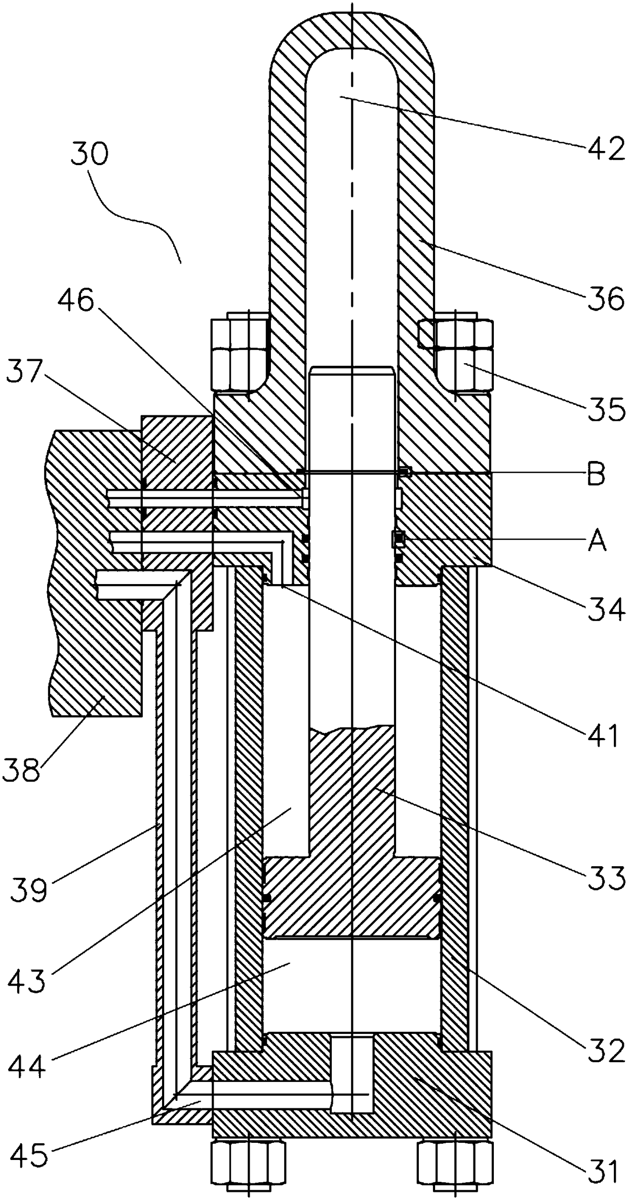
[0031] Please also see image 3 , Figure 4 , Figure 5 as well as Image 6 . in, image 3 It is a structural schematic diagram of an ultra-high pressure supercharger of the present invention; Figure 4 yes image 3 Partial enlarged view of part A shown; Figure 5 yes image 3 Partial enlarged view of Part B shown; Image 6 It is a three-dimensional schematic view of the ultra-high pressure supercharger of the present invention.

[0032] An ultra-high pressure sup...


PUM


Abstract

The invention relates to an ultrahigh pressure supercharger which comprises a low-pressure flange, a low-pressure cylinder barrel, a piston, a middle flange, an ultrahigh pressure cylinder barrel, a transitional plate, an oil way board and a connecting tube. The low-pressure flange is arranged at the bottom of the low pressure cylinder barrel, and the two ends of the middle flange are closely connected with the low-pressure cylinder barrel and the ultrahigh pressure cylinder barrel. The piston comprises a head part and a piston rod connected with the head part, the head part is closely attached to the inner wall of the low-pressure cylinder barrel, and the piston rod penetrates through the middle flange and extends into the ultrahigh pressure cylinder barrel. The oil way board and the transitional plate are sequentially mounted on the side portion of the middle flange through bolts. The ultrahigh pressure supercharger is reasonable in structural design and capable of sealing the pressure from 0 MPa to 80 MPa, guarantees the reliability of sealing, reduces external pipelines, lowers oil leakage potential hazards, and meanwhile increases the attractiveness.

Description

technical field [0001] The invention relates to the technical field of ultrahigh pressure, in particular to an ultrahigh pressure supercharger. Background technique [0002] Ultra-high pressure boosters are used in many fields, such as hydraulic cutting machines, internal high-pressure forming equipment, hydraulic presses, etc. There are two common structural principle forms for the traditional conventional turbocharger cylinders used in hydraulic presses: [0003] see figure 1 , which is a schematic structural diagram of a conventional ultra-high pressure supercharger. Such as figure 1 As shown, a traditional super high pressure booster 10 includes a cylinder 12, a first flange 11 arranged at the bottom of the cylinder 12, and a second flange 14 arranged at the top of the cylinder 12; the first method The flange 11, the second flange 14 and the cylinder 12 are tightly connected by a tie rod 15 and bolts; a movable piston 13 is arranged inside the cylinder 12, and the la...

Claims


Application Information

Patent Timeline
Patent Type & Authority Applications(China)
IPC IPC(8): F15B3/00F15B15/14
CPCF15B3/00F15B15/1423F15B15/1428
Inventor 陈爱民
Owner KEDA INDUSTRIAL GROUP CO LTD
Why Eureka
Try Eureka