Tank internal pipe line, in particular in fuel tanks of motor vehicles

一种燃料箱、储箱的技术,应用在用于储箱,能够解决制造成本昂贵、损害燃料系统功能、燃料系统损坏等问题,达到简单且制造、便宜制造、突出耐温性的效果

Inactive Publication Date: 2018-11-02
TI AUTOMOTIVE FULDABRUCK
View PDF6 Cites 0 Cited by
  • Summary
  • Abstract
  • Description
  • Claims
  • Application Information

AI Technical Summary

Problems solved by technology

These flushes impair the functionality of the fuel system in a detrimental manner and in the long run can lead to damage and / or failure of the fuel system
Furthermore, the internal pipes known from practice for tanks often have a delicate structure and are therefore expensive to manufacture
Furthermore, the durability of internal piping for tanks known in practice under mechanical and chemical loads is generally far from ideal

Method used


Image

  • Tank internal pipe line, in particular in fuel tanks of motor vehicles
  • Tank internal pipe line, in particular in fuel tanks of motor vehicles

Examples


Embodiment Construction

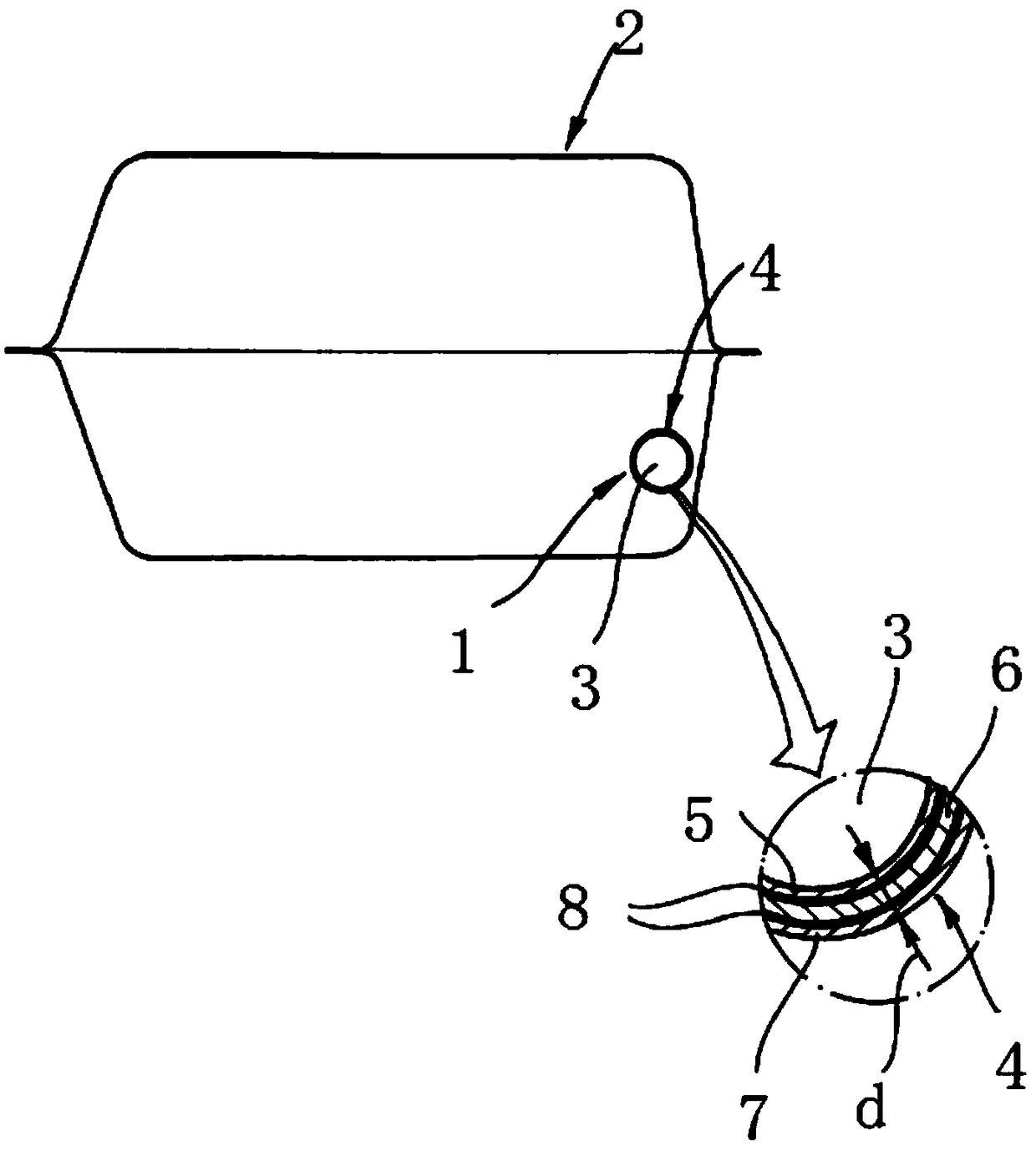
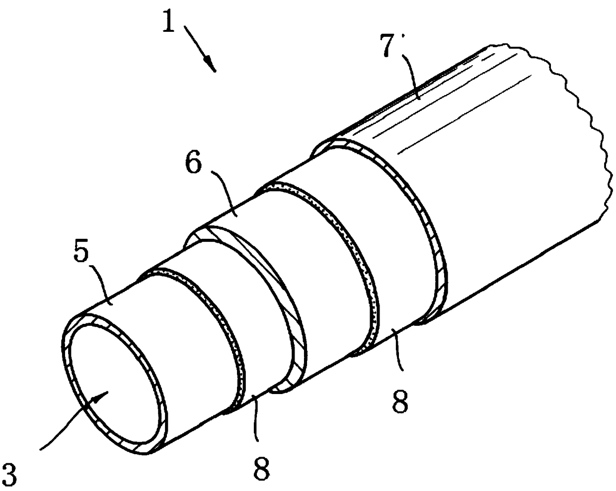
[0028] The figures show an internal conduit 1 for a tank according to the invention, which, as in the exemplary embodiment, is preferably arranged in a fuel tank 2 of a motor vehicle. In principle, different types of fuel, such as gasoline or diesel fuel, can be present in the fuel tank 2 in which the internal pipe 1 for a tank according to the invention is arranged. An internal pipe 1 for a tank has a fluid channel 3 and a pipe wall 4 surrounding the fluid channel 3 . Preferably, and in this exemplary embodiment, the tube wall 4 surrounding the fluid channel 3 has five layers. Preferably, and in this exemplary embodiment, the inner layer 5 is based on high density polyethylene (HDPE). Furthermore, the inner layer 5 can have additives, such as conductive additives, stabilizing additives, and the like. Conveniently, and in the exemplary embodiment, the inner layer 5 is followed by an adhesion promoter layer which improves the adhesion between the inner layer 5 and the layer i...


PUM


Abstract

An internal tube for tanks, particularly fuel tanks of automobiles, wherein the tube has a fluid channel and a tube wall that encloses the fluid channel, wherein the tube wall has a multilayer designand is composed of at least three layers, with one inner layer based on at least one polyolefin being provided, with at least one central layer based on at least one polyamide being present, and withone outer layer based on at least one polyolefin being provided.

Description

technical field [0001] The invention relates to an internal conduit for a tank, in particular a motor vehicle fuel tank, wherein the conduit has a fluid channel and a tube wall surrounding the fluid channel. The invention also relates to a tank having at least one such internal duct for the tank inside the tank. Background technique [0002] Internal lines for tanks and for vehicle fuel tanks of the type mentioned at the outset are known from practice in various designs. It is also known to implement these internal ducts for tanks in a multi-layer design. However, the internal pipes for tanks known in practice often have the disadvantage that components are washed out of the walls of the internal pipes for tanks due to contact with fluids, for example with fuel. This problem arises, on the one hand, due to the fluid flowing in the pipes, and, on the other hand, due to the fluid located inside the tank coming into contact with the internal pipes for the tank. These flushes...

Claims


Application Information

Patent Timeline
Patent Type & Authority Applications(China)
IPC IPC(8): F16L9/12B32B27/08B32B27/30B32B27/32B32B27/34B32B7/12B32B27/20B32B1/08
CPCF02M37/0011B32B7/12B32B27/18B32B27/32B32B3/28B32B2250/05B32B2250/40B32B2264/108B32B2270/00B32B2307/302B32B2307/732B32B2605/00B60K2015/03493B60K15/03B32B27/08B32B1/08B32B27/327B32B27/34B60K15/01B32B2597/00B32B2250/24B32B2307/202B32B2250/03B60K15/03177B32B2323/043B32B2377/00B32B2309/105F16L11/10F16L11/04B32B27/36F16L11/11F16L11/1185
Inventor 沃纳·齐默弗兰克·法伦霍尔茨马赛厄斯·鲍曼
Owner TI AUTOMOTIVE FULDABRUCK
Why Eureka
Try Eureka