Ultrasonic elastic imaging device and elastic imaging result evaluation method
A result evaluation and elastic imaging technology, applied in image enhancement, image analysis, image data processing, etc., can solve problems such as doctors' diagnostic troubles and errors
- Summary
- Abstract
- Description
- Claims
- Application Information
AI Technical Summary
Problems solved by technology
Method used
Image
Examples
Embodiment 1
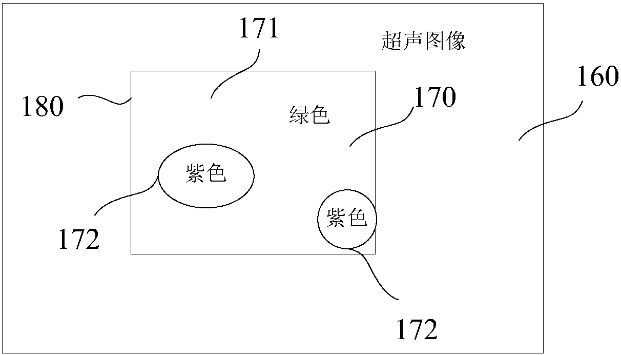
[0049] Please refer to figure 1 , the ultrasonic elasticity measurement device 100 includes an ultrasonic probe 101 , a transmit / receive sequence control module 102 , an echo processing module 104 , a processor 105 , a memory 103 and a display 106 . The processor 105 is connected to the transmit / receive sequence controller 102, the memory 103 and the display 106 respectively, the ultrasonic probe 101 is connected to the transmit / receive sequence controller 102, the ultrasonic probe 101 is also connected to the echo processing module 104, and the echo processing module 104 The output terminal of is connected to the processor 105. The device also includes a human-computer interaction device. The user interacts with the image output on the display through the human-computer interaction device, and inputs operation instructions about the selection or movement of the region of interest and / or target region to the processor. The human-computer interaction device includes: Mouse, ke...
Embodiment 2
[0082] The difference between this embodiment and the first embodiment is that the sign value representing the particle's degree of interference is the signal-to-noise ratio of the particle acceleration curve, and the signal-to-noise ratio refers to the ratio of signal to noise. When the signal-to-noise ratio of the acceleration curve is larger, it means that the acceleration curve is less affected by the noise, so the signal-to-noise ratio can also represent the degree to which the particle is affected by interference. In this embodiment, the calculation process of the signal-to-noise ratio is as follows Figure 9 shown, including the following steps:
[0083] Step 20, find the maximum amplitude of the acceleration curve. like Figure 10 As shown, search on the acceleration curve, find point A in the figure where the maximum amplitude of the acceleration curve is located, and obtain the amplitude of this point.
[0084] Step 21, select a comparison curve segment on the acc...
PUM
 Abstract
Description
Claims
Application Information
 - R&D
- Intellectual Property
- Life Sciences
- Materials
- Tech Scout
- Unparalleled Data Quality
- Higher Quality Content
- 60% Fewer Hallucinations
Browse by: Latest US Patents, China's latest patents, Technical Efficacy Thesaurus, Application Domain, Technology Topic, Popular Technical Reports.
© 2025 PatSnap. All rights reserved.Legal|Privacy policy|Modern Slavery Act Transparency Statement|Sitemap|About US| Contact US: help@patsnap.com


