This helps you quickly interpret patents by identifying the three key elements:
Problems solved by technology
Method used
Benefits of technology
Problems solved by technology
In addition, the bolts connecting the upper and lower half compartments are very large and difficult to cool
Therefore, in the methods of Patent Documents 1 and 2, it is necessary to ensure a long period of time when temporarily assembling the cabin, which greatly affects the period of work such as periodic inspection of the turbine.
In addition, when the work period is determined in advance, it may cause pressure on other processes
In addition, in the methods of Patent Documents 1 and 2, the measurement accuracy of the movement amount of the stationary body may vary due to the difference in the skill level of the surveyors, which may reduce the accuracy of the position adjustment of the stationary body, and it is difficult to apply to small turbines. Waiting for the surveyors inaccessible to the turbine
Method used
Image
Click on the blue label to locate the original text in one second.
Reading with bidirectional positioning of images and text.
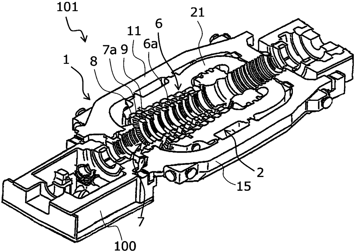
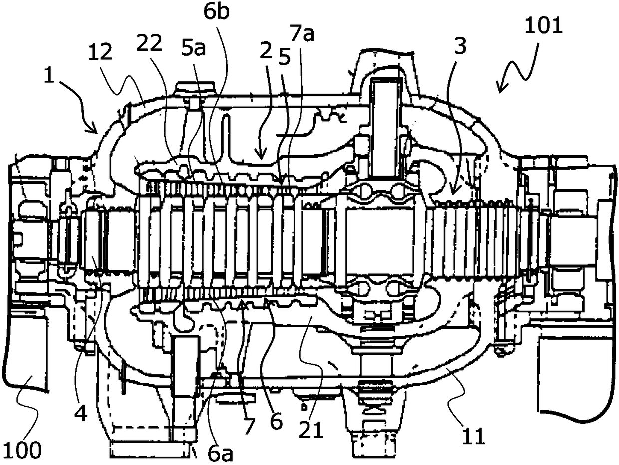
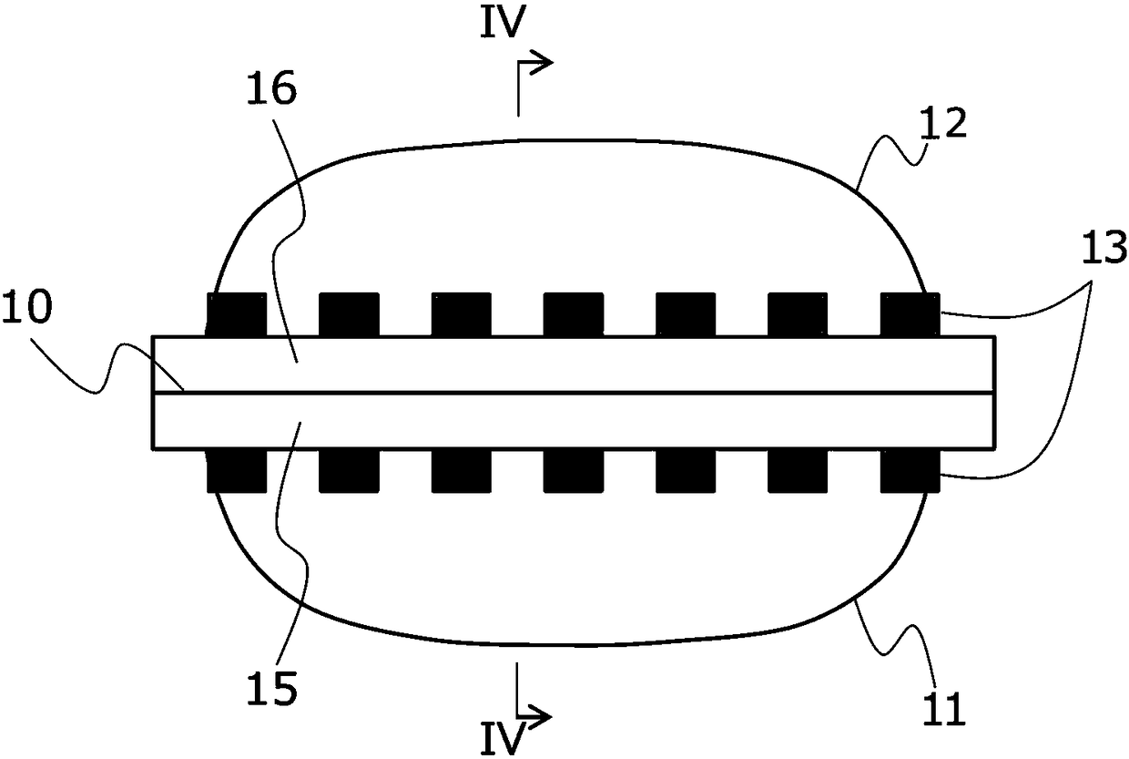
[0029] figure 1 is a perspective view showing the lower half of a steam turbine to which the assembly method according to this embodiment can be applied, figure 2 is a longitudinal sectional view showing a steam turbine to which the assembly method according to this embodiment can be applied, image 3 It is a side view showing the outer chamber of the steam turbine to which the assembly method according to this embodiment can be applied, Figure 4 yes image 3 The arrow profile of the arrow IV-IV line.
[0030] Such as figure 1 , 2 As shown, a steam turbine 101 according to this embodiment includes an outer cabin 1 supported by a frame 100 , an inner cabin 2 housed inside the outer cabin 1 , and a turbine rotor 3 enclosed in the inner cabin 2 . The load of the turbine rotor 3 is supported, for example, by a stand 100 .
[0031] Such as Figure 1~4 As shown, the outer cabin 1 is divided up and down by a horizontal plane (a plan...
no. 2 Embodiment approach >
[0104] Figure 9 It is a flowchart showing the flow of the assembly method according to this embodiment. exist Figure 9 in, right with Figure 6 In the shown flowcharts, the same steps are attached with the same symbols, and explanations thereof are appropriately omitted. Hereinafter, the assembly method according to this embodiment will be described.
[0105] The turbine assembly method according to the present embodiment is different from the turbine assembly method according to the first embodiment in that it further includes step P0. In addition, it is the same as the method of assembling the turbine according to the first embodiment.
[0106] · Step P0
[0107] The measurement data of the shapes of the upper half cabin and the lower half cabin during manufacture are acquired, and the acquired measurement data of the shapes of the upper half cabin and the lower half cabin during manufacture are reflected in the turbine model. Specifically, the flow of obtaining the ...
no. 3 Embodiment approach >
[0113] Figure 10 It is a flowchart showing the flow of the assembly method according to this embodiment. exist Figure 10 in, right with Figure 9 In the shown flowcharts, the same steps are attached with the same symbols, and explanations thereof are appropriately omitted. Hereinafter, the assembly method according to this embodiment will be described.
[0114] This embodiment is suitable for installation of steam turbines at the time of construction of a power plant equipped with steam turbines. Specifically, the assembling method according to the present embodiment differs from the assembling method according to the second embodiment in that step B1a is provided instead of step B1, and step P1a is provided instead of step P1. In addition, it is the same as the assembly method concerning 2nd Embodiment.
[0115] · Step B1a
[0116] The lower half of the outer compartment 11, the lower half of the inner compartment 21 and the bearings are provided. Specifically, the l...
PUM
Abstract
The invention is directed to maintaining the accuracy in the positional adjustment of a stationary part while shortening a turbineassembly period through the omission of the temporary assembly of a casing. A assembling method includes gaining measurement data on the configuration of a casing upper half part not fastened to a casing lower half part; gaining measurement data on the configuration ofthe casing lower half part in an open state in which the casing upper half part and a rotor are removed and in which a stationary part is mounted; comparing measurement data on the configuration of the casing upper half part and the casing lower half part with simulation data on the configuration of the casing upper half part and the casing lower half part previously obtained to select simulationdata closest to the measurement data on the configuration of the casing upper half part and the casing lower half part; calculating, based on the selected simulation data, a change amount of the configuration of the casing upper half part and the casing lower half part when the casing upper half part is fastened to the casing lower half part in the open state; and adjusting the installation position of the stationary part inside the casing taking into account the calculated change amount.
Description
technical field [0001] The present invention relates to a turbomachine assembly method, a turbomachine assembly auxiliary system, and a recording medium. Background technique [0002] In general, a turbine cabin (inner and outer cabins) is divided into a half-shape upper half and a lower half, and is configured as a flange portion connecting the upper half and the lower half with bolts. A turbine rotor constituting a rotating body is accommodated in the chamber, and the turbine rotor rotates with respect to a diaphragm or the like constituting a stationary body or a stationary body. [0003] There is a gap (gap) between the rotating body and the stationary body covering the rotating body, and a part of steam (working fluid) can pass through the gap. Thus, in this specification, the fluid which passes through the gap between a rotating body and the stationary body opposed to it is called "leakage fluid" suitably. Providing the sealing portion on the opposing surface between...
Claims
Application Information
Patent Timeline
Application Date:The date an application was filed.
Publication Date:The date a patent or application was officially published.
First Publication Date:The earliest publication date of a patent with the same application number.
Issue Date:Publication date of the patent grant document.
PCT Entry Date:The Entry date of PCT National Phase.
Estimated Expiry Date:The statutory expiry date of a patent right according to the Patent Law, and it is the longest term of protection that the patent right can achieve without the termination of the patent right due to other reasons(Term extension factor has been taken into account ).
Invalid Date:Actual expiry date is based on effective date or publication date of legal transaction data of invalid patent.

