Zipper pull conveying equipment in zipper assembly machine and use method of zipper pull conveying equipment

A technology of transmission equipment and assembly machine, applied in the direction of application, sliding fastener components, fasteners, etc., can solve the problems of high cost and high defective rate of pull piece transmission equipment, achieve simple structure, low equipment cost, and avoid wear and tear Effect

Pending Publication Date: 2018-11-06
QUANZHOU XULIN MACHINERY MFG CO LTD
1 Cites 0 Cited by

AI-Extracted Technical Summary

Problems solved by technology

[0005] The present invention provides a pull-tab transmission device in a zipper assembly machine and its use method, the main purpose of...

Method used

By arranging pull piece positioning device 2, pull piece delivery device 4, pull piece pusher 5 three and rotating disc 1 cooperate mutually, make pull piece delivery device 4 can accurately deliver pull piece 3 to pull piece positioning In the device 2, the pull tab 3 is accurately positioned by the pull tab pusher 5 to carry out the next assembly process, which greatly reduces the defective rate produced by the existing zipper assembly machine, and has low equipment cost and energy consumption. Less, which is conducive to the large-scale production of enterprises.
[0048] With reference to Fig. 2, Fig. 3, Fig. 4, Fig. 5. The upper side of the lower output end 422 of the inclined pull piece track 42 is equipped with a spring piece 423, and when the pull piece 3 moves from the lower output end 422 of the inclined pull piece track 42 to the guide channel 431 under the push of the push knife assembly 45, the elastic piece can be pushed. Lift up. The shrapnel 423 can be a manganese steel sheet. By arranging the elastic piece 423, the movement of the pull piece 3 from the lower output end 422 of the inclined pull piece track to the guide channel 431 can be made more stable and reliable, and the wear of the pull piece can also be avoided.
[0050] With reference to Fig. 2, Fig. 3, Fig. 4, Fig. 5. Specifically, the pull-tab guide assembly 43 includes a pull-tab guide block 434, a pull-tab adjustment block 435, and a stop block 436, and the pull-tab guide block 434 is locked and fixedly connected to the side of the push knife box 48 through the stop block 436, The pull tab adjustment block 435 is locked and connected to the pull tab guide block 434 in a vertically adjustable manner, and the guide channel 431 is formed between the lower end surface of the pull tab adjustment block 435 and the upper end surface of the push knife box 48 . The lower end surface of the pull-tab adjustment block 435 is bent upward toward the side of the pull-tab track 42, which further makes the movement of the pull-tab 3 from the lower output end 422 of the pull-tab track to the guide channel 431 more stable and reliable, and further reduces wear and tear Rate. In addition, the elastic movable small piece 44 extends to the end of the guide channel 431, and the side facing th...

Abstract

Provided are zipper pull conveying equipment in a zipper assembly machine and a use method of the zipper pull conveying equipment. The zipper pull conveying equipment comprises a rotary disc, a plurality of zipper pull locating devices, a zipper pull conveying device and a zipper pull push device. The zipper pull locating devices are mounted on the rotary disc around the center of the rotary discat intervals and are used for containing zipper pulls and limiting the positions of the zipper pulls. The zipper pull conveying device is used for conveying the zipper pulls to the zipper pull locating devices and comprises a zipper pull vibration sheet, an inclined zipper pull rail, a zipper pull guide assembly, a small elastic movable block, a push cutter assembly and a first driving mechanism.The zipper push device is used for pushing the zipper pulls located on the zipper pull locating devices to enable the zipper pulls to be located on the zipper pull locating devices. According to the zipper pull conveying equipment, the zipper pull conveying device can accurately convey the zipper pulls into the zipper pull locating devices, the zipper pulls are precisely located through the zipperpull push device for the next assembling process, the defective rate generated by an existing zipper assembling machine is greatly reduced, the equipment is low in cost and energy consumption, and large-scale production of an enterprise is benefited.

Application Domain

Slide fasteners

Technology Topic

EngineeringEnergy consumption +1

Image

  • Zipper pull conveying equipment in zipper assembly machine and use method of zipper pull conveying equipment
  • Zipper pull conveying equipment in zipper assembly machine and use method of zipper pull conveying equipment
  • Zipper pull conveying equipment in zipper assembly machine and use method of zipper pull conveying equipment

Examples

  • Experimental program(1)

Example Embodiment

[0041] The specific embodiments of the present invention will be described below with reference to the drawings.
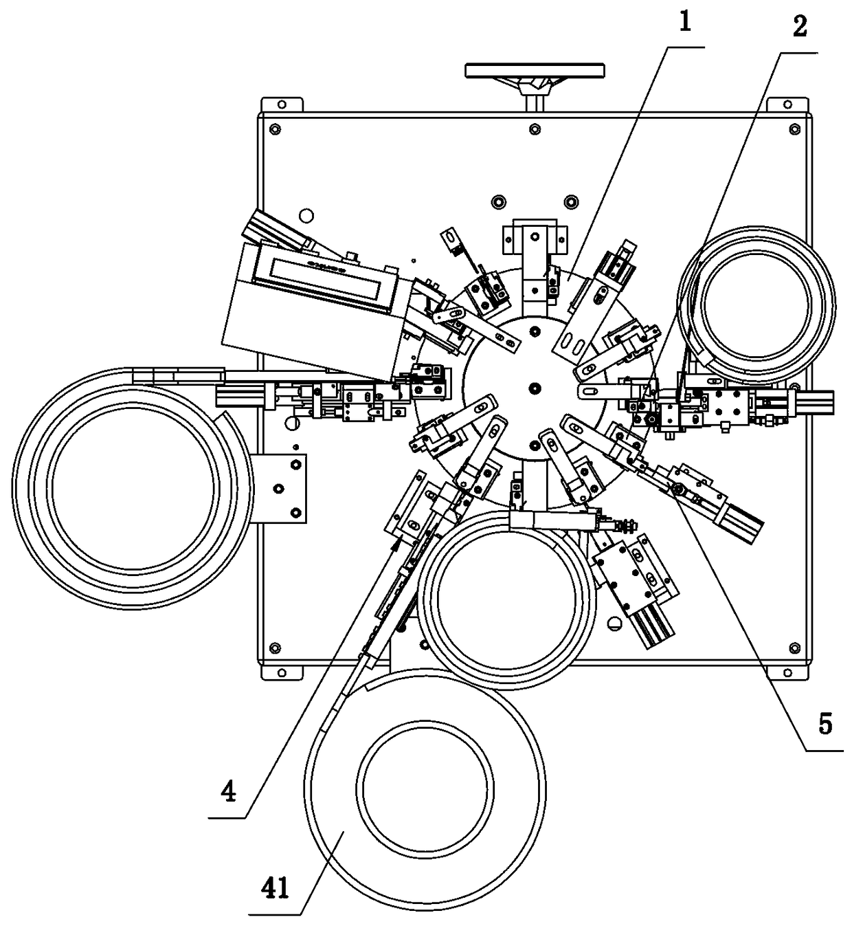
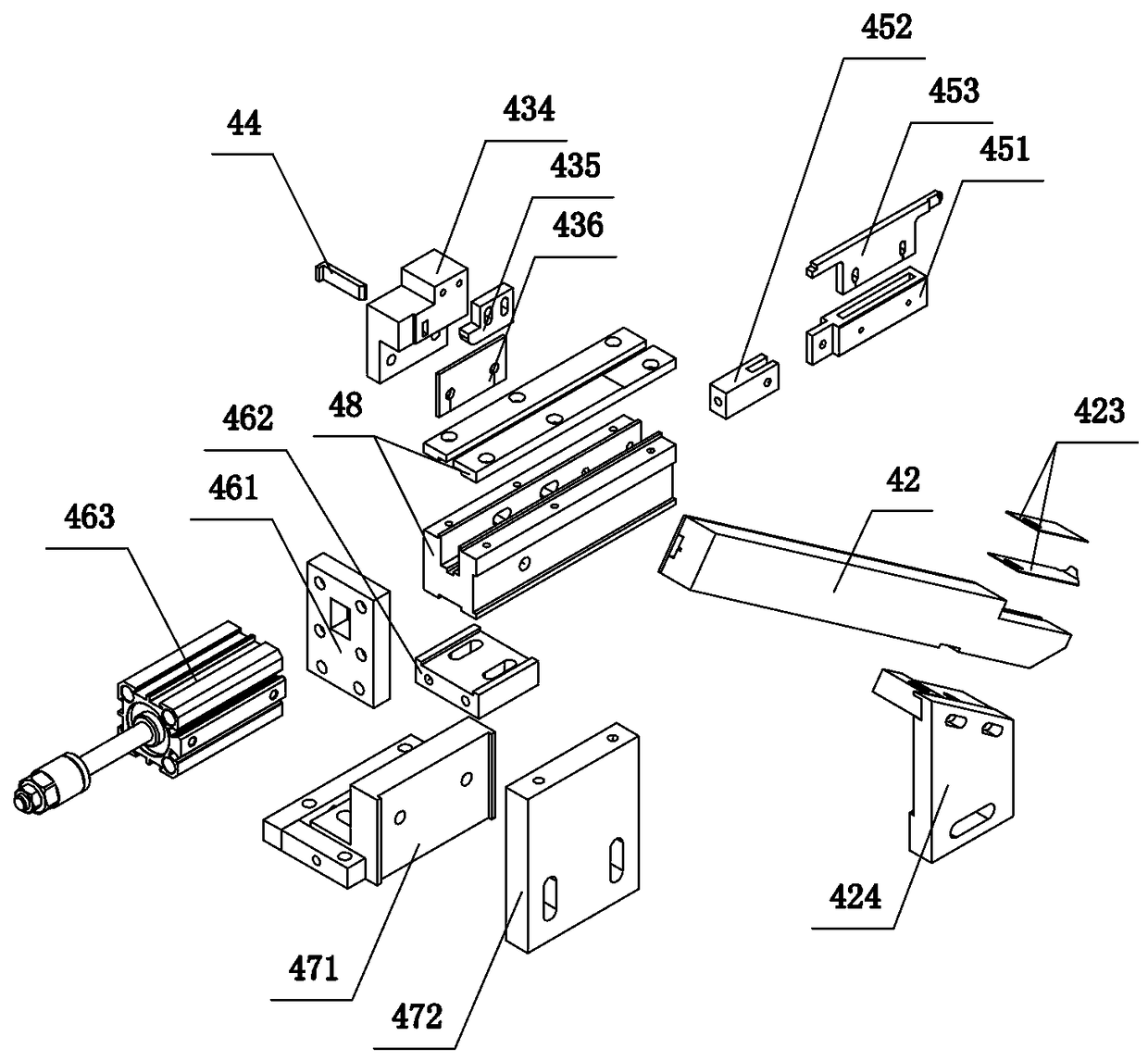
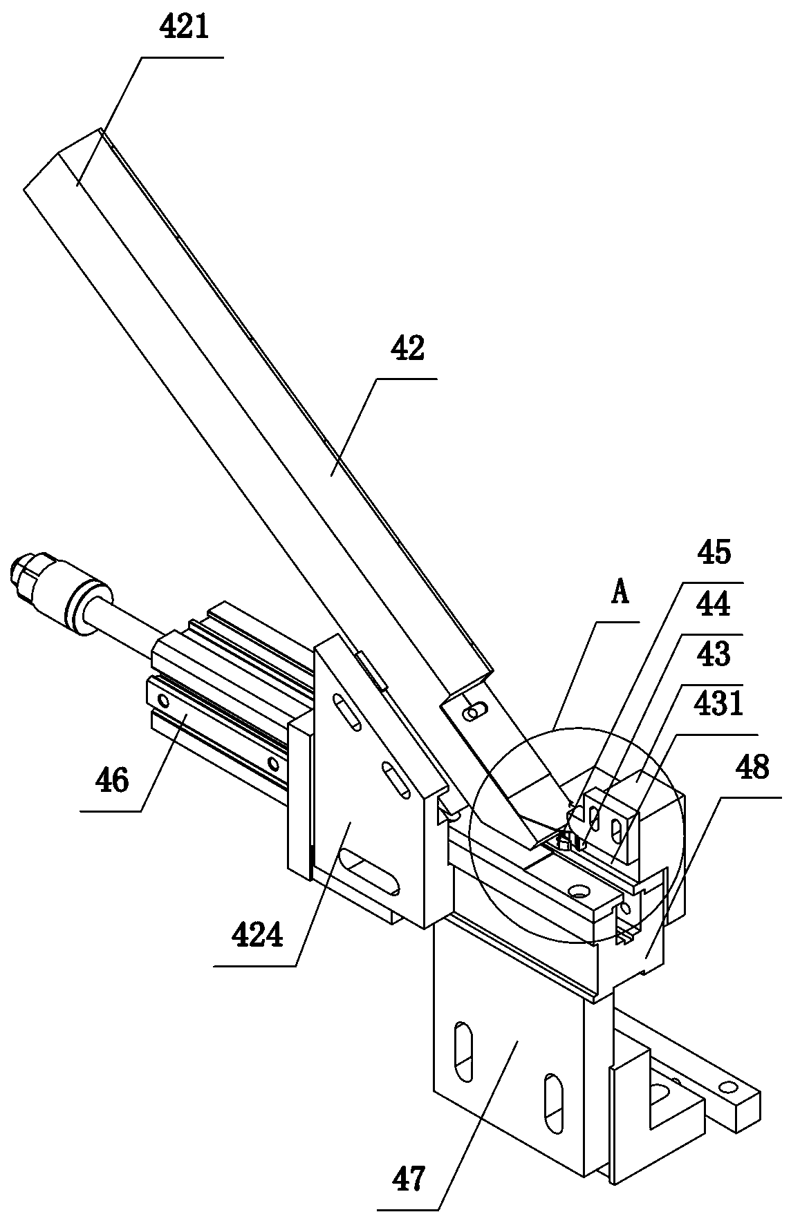
[0042] Reference figure 1 , figure 2 , image 3 , Figure 4 , Figure 5 , Image 6 , Figure 7 , Figure 8 , Picture 9 , Picture 10 , Picture 11 with Picture 12. A pull-tab conveying device in a zipper assembly machine, including
[0043] Rotate disc 1;
[0044] A plurality of pull tab positioning devices 2 are installed on the rotating disk 1 at intervals around the center of the rotating disk 1, and are used to accommodate the pull tab and define the position of the pull tab 3;
[0045] The pull-tab conveying device 4 is used to convey the pull-tab 3 to the pull-tab positioning device 2. The pull-tab conveying device 4 includes a pull-tab vibrating hopper 41, a diagonal pull-tab track 42, a pull-tab guide assembly 43, and an elastic movable block 44 , The push-knife assembly 45 and the first drive mechanism 46, the pull-tab guide assembly 43 has a guide channel 431 for the pull-tab 3 to pass through; the upper input end 421 of the diagonal pull-tab track 42 is butted with the pull-tab vibration hopper 41, The lower output end 422 is connected to the feeding side 432 of the guide channel 431; the first driving mechanism 46 is connected to the pusher assembly 45 for transmission control, and the pusher assembly 45 is driven to enable the pull tab 3 to be output from the bottom of the oblique pull tab track 422 is pushed into the guide channel 431, and then pushed into the corresponding pull-tab positioning device 2 from the discharge side 433 of the guide channel; the elastic movable piece 44 is embedded in the pull-tab guide assembly 43, and its end extends to the guide In the channel 431; when the push knife assembly 45 pushes a pull tab 3 to move past the elastic movable block 44, the elastic movable block 44 can be pressed into the pull tab guide assembly 43. After passing, the elastic movable block 44 can be ejected and Against the next pull tab;
[0046] The pull-tab pushing device 5 is used to push the pull-tab 3 on the pull-tab positioning device 2 to position the pull-tab 3 on the pull-tab positioning device 5.
[0047] By providing the pull tab positioning device 2, the pull tab conveying device 4, and the pull tab pushing device 5 to cooperate with the rotating disc 1, the pull tab conveying device 4 can accurately convey the pull tab 3 to the pull tab positioning device 2 , And then the pull tab 3 is accurately positioned by the pull tab pushing device 5 for the next assembly process, which greatly reduces the defective rate of the existing zipper assembly machine, and has low equipment cost and low energy consumption. Conducive to the large-scale production of enterprises.
[0048] Reference figure 2 , image 3 , Figure 4 , Figure 5. An elastic piece 423 is installed on the upper side of the lower output end 422 of the inclined piece track 42. When the pull piece 3 moves from the lower output end 422 of the inclined piece track to the guide channel 431 under the push of the push knife assembly 45, the elastic piece can be pushed Lift up. The elastic sheet 423 may be a manganese steel sheet. By providing the elastic piece 423, the movement of the pull piece 3 from the output end 422 under the oblique pull piece track to the guide channel 431 can be made more stable and reliable, and the pull piece can be prevented from being worn.
[0049] Reference figure 2 , image 3 , Figure 4 , Figure 5. The pull-tab conveying device 4 also includes a bracket 47 and a knife box 48 mounted on the bracket 47. The bracket 47 includes a first bracket portion 471 and a second bracket portion 472. The position of the second bracket portion 472 can be adjusted up and down to be locked. Connected to the first bracket portion 471, the push knife box 48 is locked and fixed on the upper end of the second bracket portion 472; the push knife assembly 45 is slidably mounted on the push knife box 48; the first driving mechanism 46 is connected to the cylinder fixing block 461 The push knife box 48 is fixedly connected. Specifically, the first driving mechanism 46 is connected with a cylinder fixing block 461, and the cylinder fixing block 461 is connected with a cylinder adjustment block 462. The cylinder adjustment block 462 is connected to the push knife box in an adjustable position. 48 lower end, and the position can be adjusted; the oblique piece track 42 is fixedly connected to the push knife box 48 through a track fixing block 424, specifically, the track fixing block 424 is also fixed on the side of the push knife box 48 by bolt locking, and the position can be Adjustment; The pull-tab guide assembly 43 is also fixedly installed on the side of the push knife box 48.
[0050] Reference figure 2 , image 3 , Figure 4 , Figure 5. Specifically, the pull-tab guide assembly 43 includes a pull-tab guide block 434, a pull-tab adjustment block 435, and a limit pad 436. The pull-tab guide block 434 is locked and fixedly connected to the side of the push knife box 48 through the limit pad 436. The pull-tab adjustment block 435 is connected to the pull-tab guide block 434 in a vertically adjustable manner, and the guide channel 431 is formed between the lower end surface of the pull-tab adjustment block 435 and the upper end surface of the push knife box 48. The lower end surface of the pull-tab adjustment block 435 is bent upward toward the side of the diagonal-stay track 42 to further make the movement of the pull-tab 3 from the lower output end 422 of the diagonal-stay track to the guide channel 431 more stable and reliable, and further reduce wear rate. In addition, the elastic movable piece 44 extends to the end of the guide channel 431 facing the lower output end 422 of the diagonal brace track as a slope, so as to facilitate the pull tab to compress it, and it can be guided by the spring and the tab Block 434 is connected to achieve its elastic action.
[0051] Reference figure 2 , image 3 , Figure 4 , Figure 5. Specifically, the push-knife assembly 45 includes a push-knife fixing block 451, a push-knife connecting block 452, and a push-knife 453. The first driving mechanism 46 includes a first air cylinder 463. The push-knife fixing block 451 is slidably connected in the push-knife box 48 to push One end of the knife connecting block 452 is connected to the pushing knife fixing block 451, and the other end is connected to the output end of the first air cylinder 463. The pushing knife 453 is connected to the pushing knife fixing block 451 and extends upward to the outside of the pushing knife box 48 and to the diagonal pull piece. The side surfaces of the pull tab 3 of the output end 422 under the rail 42 collide to push the pull tab to move. The material of the push knife 453 may be white steel.
[0052] Reference Image 6 , Figure 7 , Figure 8 , Picture 10. Specifically, the pull-tab pushing device 5 includes a second drive mechanism 51, a fisheye bearing 52, a pull-tab fixing slider 53, a pull-tab fixing steel sheet 54 and a pull-tab fixing small block 55, the pull-tab fixing steel sheet 54 and the pull-tab The fixed small blocks 55 are respectively and adjustably connected to the two sides of the pull-tab fixed slider 53. One end of the fisheye bearing 52 is connected to the second drive mechanism 51 for transmission control, and the other end is connected to the pull-tab fixed slider 53; in addition, it also includes The sliding groove 56, the sliding groove frame 59, and the sliding groove cover 57 covering the sliding groove 56, the pull tab fixing slider 53 is slidably installed in the sliding groove, and the second driving mechanism 51 passes through the sliding groove fixing block 58 It is fixedly connected with the sliding groove 56, and the sliding groove frame is installed at the bottom end of the sliding groove 56 to support the sliding groove; the pull-tab fixing slider 53 is driven, and the pull-tab fixing small block 55 can be connected with the pull-tab positioning device 2 The front end 31 of the pull tab 3 conflicts, and the pull tab fixing steel sheet 54 can conflict with the side surface 32 of the pull tab 3 on the pull tab positioning device, thereby positioning the pull tab on the pull tab positioning device 2.
[0053] Reference Figure 8 , Picture 9 , Picture 10 , Picture 11 with Picture 12. Specifically, the pull-tab positioning device 2 includes a fixed seat 21, a pull-tab front and rear adjustment block 22, a pull-tab upper and lower movable block 23, a pull-tab side limit block 24, and a pull-tab upper clamping plate 25. The pull-tab front and rear adjustment block 22 Adjustably locked and connected to the fixed seat 21; the upper and lower movable block 23 of the clip pull tab can be movably connected to the side of the front and rear adjustment block 22 of the clip pull tab, and conflicts with the bottom surface 33 of the pull tab 3. Specifically, A spring can be arranged at the lower end of the upper and lower movable block 23 of the clip pull piece, so that the upper and lower movable block 23 of the clip pull piece always has an upward pushing force, which plays a role of stably clamping the pull piece; the pull piece side limit block 24 is fixedly installed at The upper side of the front and rear adjusting block 22 of the pull tab is in contact with a side 34 of the pull tab 3 and can be in contact with the rear end 35 of the pull tab 3; the upper clamping plate 35 of the pull tab is fixedly installed at the side limit of the pull tab The upper side of the block 24 and the top surface 36 of the pull-tab; when the pull-tab pushing device 5 acts, the pull-tab 3 can be sandwiched between the pull-tab fixing steel sheet 54 and the pull-tab side limit block 24, and pull The tab fixing small block 55 can push the front end 31 of the pull tab 3 so that the rear end 35 of the pull tab conflicts with the side limit block 24 of the pull tab. In addition, the pull-tab positioning device 2 also includes a pin fixing block 26 and a pin 27 that are connected to each other for positioning the slider 6 of the zipper; the upper clamping plate 25 of the pull-tab is provided with a torsion spring hole 28 for positioning the torsion spring 7, and After the positioning of the tab 3, the slider 6, and the torsion spring 7 are completed, subsequent assembly is performed.
[0054] Reference figure 1 , figure 2 , image 3 , Figure 4 , Figure 5 , Image 6 , Figure 7 , Figure 8 , Picture 9 , Picture 10 , Picture 11 with Picture 12. A method for using pull-tab conveying equipment in a zipper assembly machine includes the following steps:
[0055] 1) The rotating disc 1 is rotated into position so that the upper vacant pull tab positioning device 2 is facing the pull tab conveying device 4;
[0056] 2) The pull-tab conveying device 4 is activated, and the pull-tabs 3 in the pull-tab vibrating hopper 41 are sequentially dropped into the diagonal-stay track 42 for transmission until they are delivered to the lower output end 422 of the diagonal-stay track 42 and are located at the lower output The side of the pull tab 3 of the end 422 conflicts with the push knife assembly 45;
[0057] 3) The first driving mechanism 46 acts to drive the push knife assembly 45 to move, thereby pushing the pull tab 3 that is in conflict with it to move. The pull tab 3 enters the feeding side 432 of the guide channel in the pull tab guide assembly 43 and slides into it. The elastic movable piece 44 in the pull-tab guide assembly 43 is pressed into the pull-tab guide assembly 43, and then the pull-tab 3 is pushed to the discharge side 433 of the guide channel, and then enters the opposite pull-tab positioning device 2 Then, the push-knife assembly 45 returns to its original position, and it conflicts with the next pull-tab side that falls into the output end 422 under the diagonal pull-tab track; after the pull-tab 3 leaves the elastic movable piece 44, the elastic movable piece 44 Can pop out and hold the next pull tab;
[0058] 4) After the pull tab 3 enters the pull tab positioning device 2, one side 34 of the pull tab 3 conflicts with the pull tab side limit block 24 in the pull tab positioning device 2, and the bottom surface 33 is in contact with the clip in the pull tab positioning device 2. The front and rear adjustment blocks 22 of the pull-tab collide, and the top surface 36 collides with the upper clamping plate 25 of the pull-tab positioning device;
[0059] 5) The rotating disc 1 continues to rotate until the pull-tab positioning device 2 is facing the pull-tab pushing device 5;
[0060] 6) The pull-tab pushing device 5 is activated, and the second driving mechanism 51 acts to drive the fish-eye bearing 52 to move, thereby pushing the pull-tab fixed slider 53 connected to the fish-eye bearing 52 to move, so that the slider 53 is fixed with the pull-tab The connected pull-tab fixing steel sheet 54 enters into the pull-tab positioning device 2 and interferes with the other side 32 of the pull-tab 3, and at the same time makes the pull-tab fixing small block 55 connected with the pull-tab fixing slider 53 and the pull-tab 3 The front end 31 conflicts, and then the pull tab 3 is pushed to make the rear end 35 of the pull tab conflict with the side limit block 24 of the pull tab, and the positioning of the pull tab is completed.
[0061] The foregoing are only specific implementations of the present invention, but the design concept of the present invention is not limited to this. Any insubstantial modification of the present invention using this concept should be an act that violates the protection scope of the present invention.

PUM

no PUM

Description & Claims & Application Information

We can also present the details of the Description, Claims and Application information to help users get a comprehensive understanding of the technical details of the patent, such as background art, summary of invention, brief description of drawings, description of embodiments, and other original content. On the other hand, users can also determine the specific scope of protection of the technology through the list of claims; as well as understand the changes in the life cycle of the technology with the presentation of the patent timeline. Login to view more.

Similar technology patents

Photoelectric sensor for position of sun

InactiveCN101650173AEffective tracking range expandedSimple structure
Owner:WUHAN UNIV OF TECH

Magnetic cooling apparatus and control method thereof

ActiveUS20130180263A1simple structure
Owner:SAMSUNG ELECTRONICS CO LTD

Dual-Drivetrain of Power-Assist Vehicle

InactiveUS20100181130A1enhance uphill momentumsimple structure
Owner:CHOU WEN CHENG

Classification and recommendation of technical efficacy words

  • Simple structure
  • Practical

User behavior self-learning air conditioning system and control method thereof

ActiveCN105318499AConvenience and good experiencePractical
Owner:GD MIDEA AIR-CONDITIONING EQUIP CO LTD +1

Optimization method for spray gun track of spraying robot on irregular polyhedron

ActiveCN102500498APracticalImprove work efficiency and product quality
Owner:JIANGSU NEWBLUE INTELLIGENT EQUIP CO LTD

Intelligent grid comprehensive evaluating system based on analytic hierarchy process and fuzzy comprehensive evaluation

InactiveCN102663508ADemonstrate economic and social benefitsPractical
Owner:NORTHEAST POWER SCI RES INSTITUTION +2
Why Eureka
Try Eureka