
Light spot trajectory control device in laser dental preparation robot

A control device and robot technology, applied in dentistry, prosthodontics, dental tools, etc., can solve the problems of difficult positioning of tooth locators, inability to meet accuracy requirements, light blocking and other problems

Inactive Publication Date: 2020-10-23
UNIV OF ELECTRONICS SCI & TECH OF CHINA
View PDF1 Cites 0 Cited by
  • Summary
  • Abstract
  • Description
  • Claims
  • Application Information

AI Technical Summary

Problems solved by technology

This laser trajectory control method can realize the three-dimensional cutting of the tooth, but it has obvious disadvantages: First, because the laser can only be cut after focusing, there is a convergence angle. When the laser is incident on the tooth surface at an angle close to the vertical, with the cutting As the depth increases, the phenomenon of light blocking will occur, and peeling cutting can not be realized, and the cutting efficiency will be low. Second, the tooth locator itself is difficult to locate. The direction of the long axis is inconsistent. When the angle between the Z-axis direction of the positioner and the long axis of the tooth is greater than 5°, it will cause the cutting to fail to meet the precision requirements of the tooth preparation

Method used


Image

  • Light spot trajectory control device in laser dental preparation robot
  • Light spot trajectory control device in laser dental preparation robot
  • Light spot trajectory control device in laser dental preparation robot

Examples


Embodiment Construction

[0040] The present invention will be further described in detail below in conjunction with examples, but the embodiments of the present invention are not limited thereto.

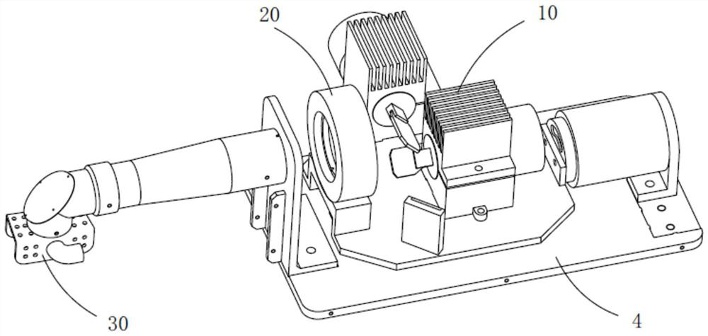
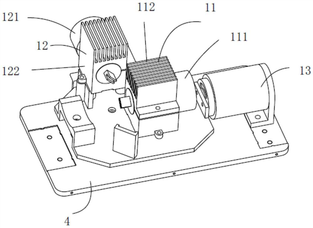
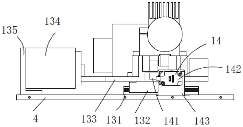
[0041] figure 1 It is a schematic diagram of the overall structure of the spot track adjustment device according to an embodiment of the present invention, as figure 1As shown, a light spot trajectory control device in a laser tooth preparation robot includes an optical path assembly 20, a drive assembly 10, a tooth positioning assembly 30, and a substrate 4; the drive assembly 10 can be an assembly driven by a motor, the device of an embodiment The main working principle of the invention is that the motor driving component drives the two vibrating mirrors in the two optical path components 20 to oscillate, so as to realize the scanning of the light spot in the X and Y directions. In one embodiment, the driving assembly 10 can use a voice coil linear motor to drive the sliding plate 133 to drive the two os...


PUM


Abstract

The invention discloses a light spot trajectory control device in a laser tooth preparation robot, which includes a drive assembly, an optical path assembly, and a tooth positioning assembly. In the drive assembly, the X vibration mirror swing motor is installed on the X vibration mirror motor base, and the Y vibration mirror The swing motor is installed on the Y vibrating mirror motor base, the two vibrating mirror drive components are fixed on the slide plate, and the slide plate drive component is installed on the base plate; in the optical path components, the X vibrating mirror is mounted on the X vibrating mirror swing motor, and the Y vibrating mirror is mounted on the On the Y vibrating mirror swing motor, the focusing lens is fixed on the lens holder of the slide plate; in the tooth positioning assembly, the tooth aligner adopts a translational transmission mechanism, and the tooth positioner is positioned by cooperating with the tooth aligner. The invention realizes the control of the track of the light spot, and solves the problem of light blocking and the positioning of the tooth locator itself in the stripping cutting process in the prior art, and improves the efficiency and accuracy of tooth preparation.

Description

technical field [0001] The invention relates to the technical field of oral surgical instruments, in particular to a light spot trajectory control device in a laser tooth preparation robot. Background technique [0002] At present, in dental oral treatment, it is sometimes necessary to cut tooth hard tissue quantitatively. Dental handpieces are currently the most commonly used tooth preparation tools. The working principle of the dental handpiece is to grind and remove all sides of the teeth through the high-speed rotating bur in the handpiece to meet clinical requirements. The whole process of tooth preparation is carried out by the doctor, and the shape after preparation is also judged by the doctor through experience. This method has obvious disadvantages. First, the oral cavity space is small, and the operation needs to be controlled by the operator's vision and hand positioning. Too much or insufficient tooth preparation often occurs, and even causes iatrogenic damage...

Claims


Application Information

Patent Timeline
Patent Type & Authority Patents(China)
IPC IPC(8): A61C3/02
CPCA61C3/02
Inventor 范守文罗志竞曲兴家牛大山朱晖范帅
Owner UNIV OF ELECTRONICS SCI & TECH OF CHINA
Learn More