Plant Ventilation and Ventilation Devices

A ventilation device and plant technology, which is applied in the direction of dry gas arrangement, gas treatment, separation methods, etc., can solve the problems of no reuse, tea dust dumping, etc., and achieve the effect of improving the use efficiency

Active Publication Date: 2021-08-31
MEITAN COUNTY LUOHUATUN TEA PROFESSIONAL COOP
View PDF5 Cites 0 Cited by
  • Summary
  • Abstract
  • Description
  • Claims
  • Application Information

AI Technical Summary

Problems solved by technology

[0003] The purpose of the present invention is to provide a plant ventilation device to solve the problem that the tea dust in the air in the traditional tea factory is often directly dumped after being collected and not reused

Method used


Image

  • Plant Ventilation and Ventilation Devices
  • Plant Ventilation and Ventilation Devices
  • Plant Ventilation and Ventilation Devices

Examples


Embodiment 1

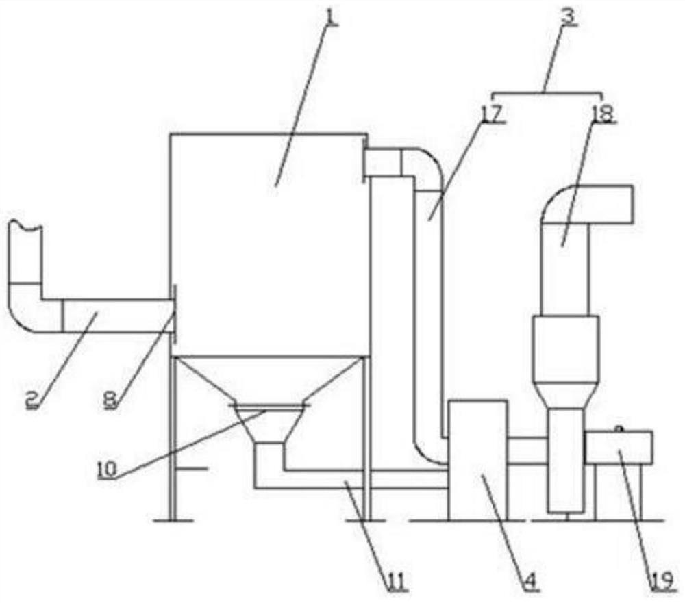
[0018] Embodiment 1: as figure 1 As shown, the factory building ventilation device includes a central dust collector 1, a heat preservation gas collection pipe 2, an air outlet pipe 3 and a combustion furnace 4. The air inlet 8 of the central dust collector 1 is connected to the heat preservation gas collection pipe 2, and the air outlet is connected to the The inlet of the pipeline 3 is connected, and the dust outlet 10 is connected to the feed port of the combustion furnace 4; the gas outlet pipeline 3 is located in the heating area of ​​the combustion furnace 4, and the gas outlet pipeline 3 is connected to the drying and heating chamber in the factory building.

[0019] In this embodiment, the heat preservation and gas collection pipeline 2 is arranged above each device in the workshop, which is used to collect the tea dust generated during tea processing, the central dust collector 1 is used to separate the tea dust in the air, and the air outlet pipeline 3 is used to dis...

Embodiment 2

[0021] Such as figure 2 As shown, compared with Example 1, this embodiment optimizes the central dust collector 1. The central dust collector 1 includes a dust removal filter box 5, and a filter bag 6 is arranged in the dust removal filter box 5. The filter bag 6 is fixedly installed on the dust removal filter box through a skeleton 7 In the box 5, and vertically above the air inlet 8, the top of the filter bag 6 is open, and the pulse injection device 9 is arranged above the filter bag 6, and the suction port of the pulse injection device 9 and the filter bag The top openings of 6 are arranged oppositely in the vertical direction; the dust outlet 10 is arranged on the bottom of the dust filter box 5, and is connected with the feed port of the combustion furnace 4 through the feed pipe 11.

[0022] In this embodiment, since the central dust collector 1 is used for a long time, a large amount of dust will accumulate on the filter bag 6 in the dust filter box 5, which will affe...

Embodiment 3

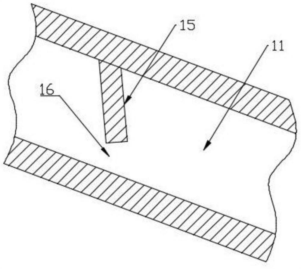
[0024] Such as figure 1 , 2 As shown, compared with embodiment 2, the present embodiment optimizes the material guide pipeline 11, the material guide pipeline 11 is arranged downwardly from the dust removal filter box 5 to the combustion furnace 4 places, and the material guide pipeline 11 is respectively connected with the elastic hose 12 The dust removal filter box 5 is connected with the combustion furnace 4, and a heat insulating layer is laid on the pipe wall of the material guide pipe 11.

[0025] In the present embodiment, the material guide pipe 11 is inclined downward from the dust removal filter box 5 to the combustion furnace 4, so that the collected tea dust can move downwards by gravity, so as to facilitate entering the combustion furnace 4, and guide The material pipeline 11 is respectively connected with the dust removal filter box 5 and the combustion furnace 4 through the elastic hose 12, and the elastic hose 12 enables the material guide pipeline 11 to move,...


PUM


Abstract

The invention discloses a ventilation and ventilation device for a factory building, comprising a central dust collector, a thermal insulation gas collection pipe, an air outlet pipe and a combustion furnace. The dust outlet is connected with the feed inlet of the combustion furnace; the gas outlet pipe is located in the heating zone of the combustion furnace, and the gas outlet pipe is connected to the drying and heating chamber in the workshop; the beneficial effect of the invention is: The dust is collected, and then the tea dust is burned through the combustion furnace, so that the heat of the combustion of the tea dust is used to heat the air outlet pipe, and then the heated air is discharged into the drying and heating chamber for heating and drying the tea leaves, which not only ensures the The air in the workshop also burns and reuses the tea dust, which improves the use efficiency of the tea dust.

Description

technical field [0001] The invention relates to a ventilation device, in particular to a factory building ventilation device. Background technique [0002] When tea leaves are picked, processed and produced to finished tea, there are many processes in the middle. Generally, tea processing is carried out in tea factories, but a large amount of tea dust will be generated during tea processing and production. Tea dust floating in the air will damage the The health of production personnel is affected. At present, dust removal equipment is used in tea factories to filter the air in the tea factory, but the filtered tea dust is often poured out directly and is no longer used. Contents of the invention [0003] The purpose of the present invention is to provide a factory building ventilation device, which solves the problem that the tea dust in the air in the traditional tea factory is often directly dumped after being collected without reuse. [0004] In order to solve the abov...

Claims


Application Information

Patent Timeline
Patent Type & Authority Patents(China)
IPC IPC(8): B01D46/02B01D46/04F23G7/06F26B21/00
CPCB01D46/02B01D46/04B01D2258/06F23G7/06F23G2206/20F26B21/001F26B2200/20
Inventor 彭忠
Owner MEITAN COUNTY LUOHUATUN TEA PROFESSIONAL COOP
Why Eureka
Try Eureka