Special processing machine and processing method for auto decelerator shell

A technology for reducer housings and automobiles, which is applied in the direction of metal processing machinery parts, metal processing equipment, manufacturing tools, etc. It can solve the problems of unstable parts quality, poor verticality, and high skill requirements for debugging personnel, so as to reduce the difficulty of debugging and improve The effect of stability and debugging process is simple and convenient

Pending Publication Date: 2018-11-06
SICHUAN JIANAN IND
View PDF0 Cites 3 Cited by
  • Summary
  • Abstract
  • Description
  • Claims
  • Application Information

AI Technical Summary

Problems solved by technology

When the three-head boring machine is processing the shell reduction, the rear slide table processes the differential bearing hole, the left slide table tool bar processes the large main tooth bearing hole, and the right slide table tool bar processes the small main tooth bearing hole and oil seal hole. The working status of the table is different, and the length of time causes the cutter rod of the power head of the left and right sliding table to be out of concentricity, which in turn causes the coaxiality, offset distance, and verticality of the large and small bearing holes of the parts to be out of tolerance, and the quality of the parts is unstable.
Every time the machine tool is debugged, the left and right power heads must be adjusted at the same time, which is difficult, inefficient, and requires high skills for the debuggers

Method used


Image

  • Special processing machine and processing method for auto decelerator shell
  • Special processing machine and processing method for auto decelerator shell
  • Special processing machine and processing method for auto decelerator shell

Examples


Embodiment Construction

[0020] The present invention will be further described below in conjunction with accompanying drawing.

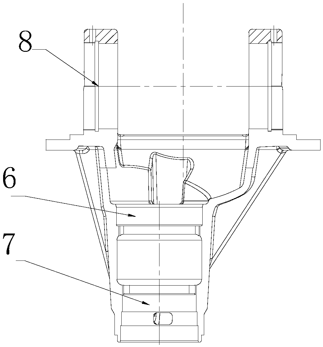
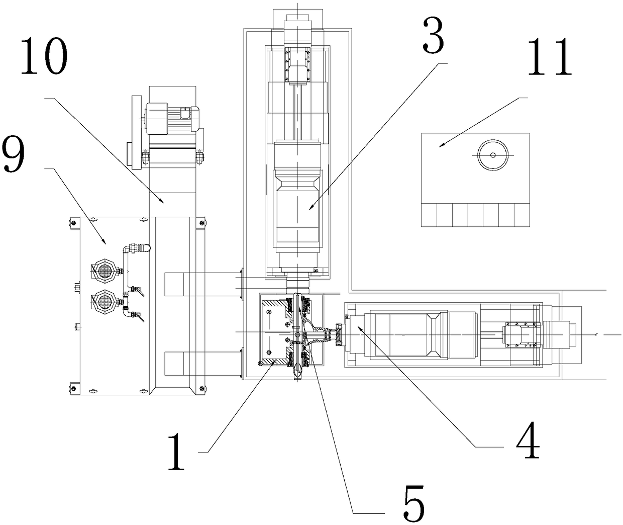
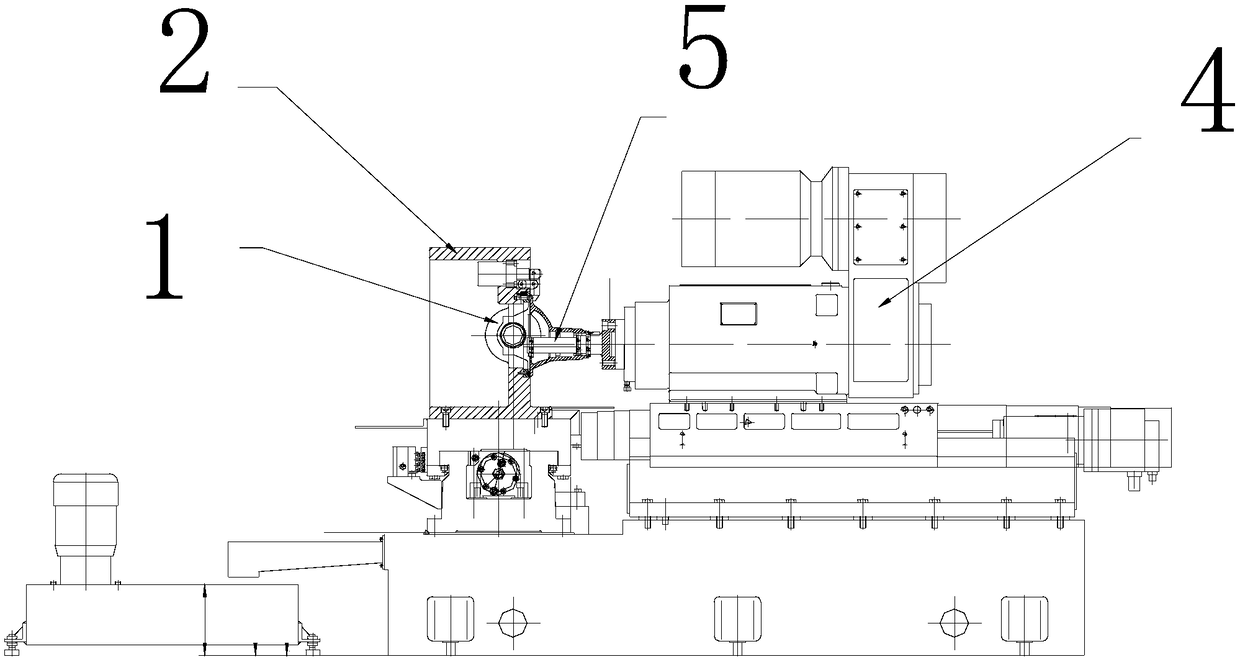
[0021] The structure of the parts of the reducer housing is as follows: figure 1 shown. Such as figure 2 with image 3 As shown, the special double-head boring machine for automobile reducer housing of the present application includes a workpiece fixture 2, a horizontal slide table, a vertical slide table, a horizontal boring processing head 3 and a longitudinal boring processing head 4, and the horizontal boring processing head The axis of 3 is perpendicular to the axis of the longitudinal boring processing head 4, the horizontal boring processing head 3 is installed on the horizontal sliding table, the longitudinal boring processing head 4 is installed on the longitudinal sliding table, the horizontal boring processing head 4 The processing head 3 includes a drive motor and a cutter bar 5 that is transmission-connected with the output shaft of the drive motor. The fro...


PUM


Abstract

The invention discloses a special processing machine and a processing method for an auto decelerator shell, and in particular relates to the special processing machine and the processing method for the auto decelerator shell in the field of auto decelerator shell processing. The special double-end boring machine for the auto decelerator shell comprises a workpiece clamp, a transverse slipway, a longitudinal slipway, a transverse boring head and a longitudinal boring head, wherein a boring cutter is arranged at the front end of a cutter bar. The processing method for the auto decelerator shellcomprises the following steps: A, clamping the decelerator shell on a clamp; B, feeding to an appointed processing position; C, processing a big main gear bearing hole and a small main gear bearing hole, and processing a bearing hole of a differential simultaneously; and D, stopping the cutter bar directionally and moving the clamp to relieve the cutter. The special processing machine and the processing method disclosed by the invention solve the problem of coaxiality of main gear bearing holes, the offset and perpendicular dimension are controlled effectively, the quality reliability of a product is improved, and meanwhile, the maintenance and debugging difficulty of the equipment is reduced greatly.

Description

technical field [0001] The invention relates to a special machine and a processing method for processing an automobile reducer shell, in particular to a special machine and a processing method for processing an automobile reducer shell which relate to the field of processing the automobile reducer shell. Background technique [0002] The automobile reducer housing is an important part of the automobile reducer. The part is equipped with mounting holes for installing the large main tooth bearing, the small main tooth bearing and the differential gear bearing. Among them, the coaxiality, offset distance, and verticality requirements of the large main tooth bearing hole and the small main tooth bearing hole are relatively high. In the prior art, a special three-head boring machine is used to process the aforementioned three holes. When the three-head boring machine is processing the shell reduction, the rear slide table processes the differential bearing hole, the left slide ta...

Claims


Application Information

Patent Timeline
Patent Type & Authority Applications(China)
IPC IPC(8): B23B41/00B23B39/02B23Q1/25B23Q11/10
CPCB23B41/00B23B39/02B23Q1/25B23Q11/10
Inventor 卢成勇赖祥华郝峰陆鹏谭战武
Owner SICHUAN JIANAN IND
Why Eureka
Try Eureka