Method for prediction of flutter in numerical-control milling of mold cavities

A CNC milling and cavity technology, applied in milling machine equipment, manufacturing tools, details of milling machine equipment, etc., can solve the problems affecting the processing quality of mold cavity, low accuracy of milling chatter prediction, and speed up tool failure, etc., to achieve the prediction process Convenience and quickness, accurate chatter prediction, and guaranteed processing quality

Inactive Publication Date: 2018-11-06
HARBIN UNIV OF SCI & TECH
View PDF5 Cites 2 Cited by
  • Summary
  • Abstract
  • Description
  • Claims
  • Application Information

AI Technical Summary

Problems solved by technology

[0004] The purpose of the present invention is to solve the problem that the existing single tool path milling stability prediction method has low applicability, which leads to low milling chatter prediction accuracy, accelerates tool failure, and affects the processing quality of the mold cavity, and proposes a prediction Method of Chatter in NC Milling of Mold Cavity

Method used


Image

  • Method for prediction of flutter in numerical-control milling of mold cavities
  • Method for prediction of flutter in numerical-control milling of mold cavities
  • Method for prediction of flutter in numerical-control milling of mold cavities

Examples


specific Embodiment approach 1

[0031] Specific implementation mode 1: A method for predicting flutter in CNC milling of mold cavity in this implementation mode The specific process is as follows:

[0032] Step 1. Establishing the relative transfer function of the tool-workpiece system;

[0033] Obtaining the dynamic characteristics of the tool-workpiece system, that is, the transfer function matrix, is an important prerequisite for predicting the stability of the milling process. Most of the previous studies only considered the dynamic characteristics of the tool system, while ignoring the influence of the workpiece system on the dynamic characteristics of the overall machining system. The present invention comprehensively considers the dynamic characteristics of the tool subsystem and the workpiece subsystem, and establishes The overall dynamics model of the tool-workpiece system.

[0034] Obtain the transfer functions of the tool subsystem and workpiece subsystem separately

[0035] G ci (jω)=X ci (jω...

specific Embodiment approach 2

[0042] Embodiment 2: The difference between this embodiment and Embodiment 1 is that in Step 2, the relative transfer function of the tool-workpiece system obtained in Step 1 is introduced into the three-dimensional milling stability model to obtain the milling chatter frequency of the milling cutter The critical axial depth of cut at ; the specific process is:

[0043] Three-dimensional milling stability model based on the frequency domain method. During the process of milling the side of the mold cavity by the milling cutter, the tangential force F t Distribution along the direction of milling speed along the milling edge of the milling cutter, the radial force F r is the radial direction of the milling cutter feed, the axial force F aActing in the axial direction of the milling cutter; in order to consider the general case, in the milling edge line, the milling edge is divided into a finite number of small differential units. The chip loads and corresponding differential ...

specific Embodiment approach 3

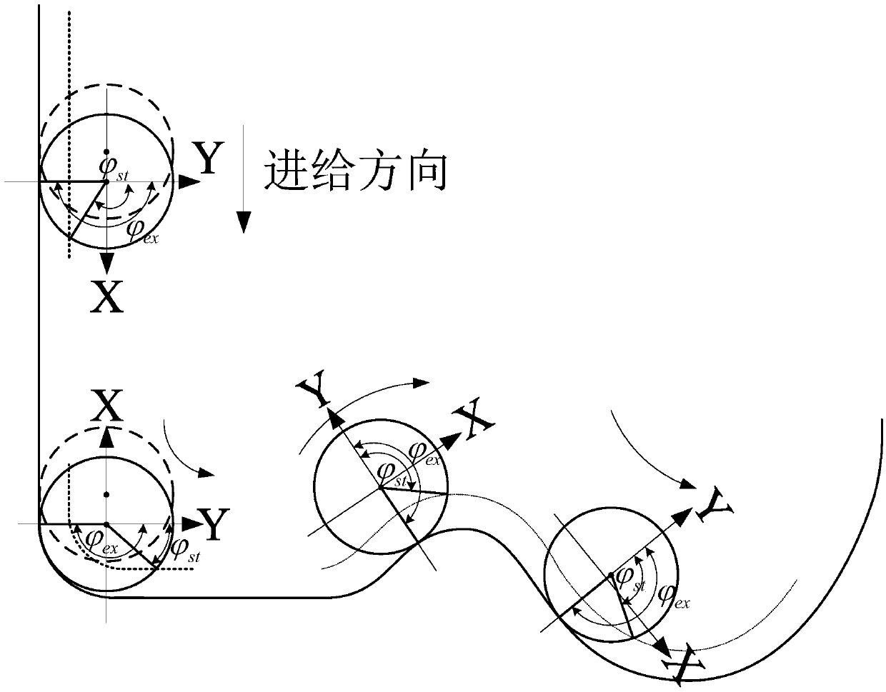
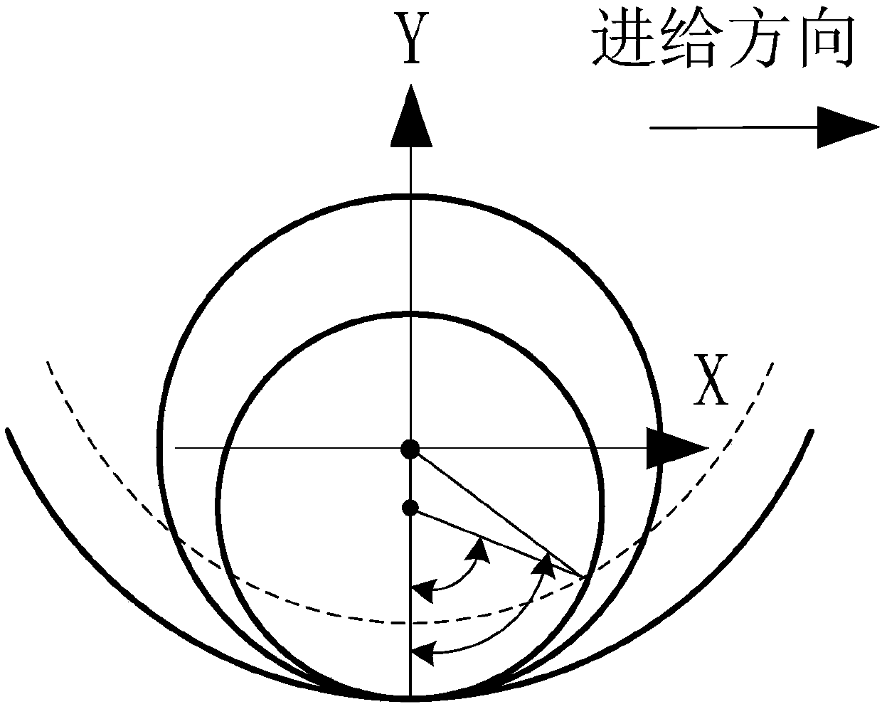
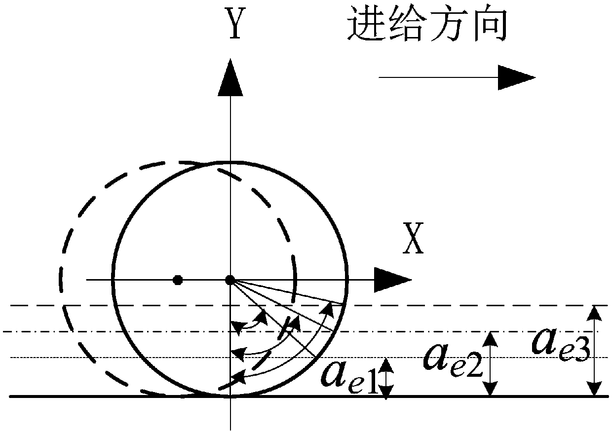
[0100] Embodiment 3: The difference between this embodiment and Embodiment 1 or 2 is that: when the tool is down milling, the horizontal cutting angle and cutting angle of the cutter tooth are respectively and The formula is:

[0101]

[0102] In the formula, R c is the tool radius, a e is the radial depth of cut;

[0103] When the tool is up milling, the horizontal entry angle and exit angle of the cutter tooth are respectively and The formula is:

[0104]

[0105] Other steps and parameters are the same as those in Embodiment 1 or Embodiment 2.


PUM


Abstract

The invention relates to a method for prediction of flutter in numerical-control milling of mold cavities, aiming to solve problems that conventional methods for predicting stability in milling utilizing single tool path are low in applicability, which causes low accuracy of flutter prediction, accelerates failure of tools and affects processing quality of mold cavities. The method for predictionof flutter in numerical-control milling of mold cavities includes the step 1, building the relative transfer function of a tool-workpiece system; the step 2, introducing the relative transfer function of the tool-workpiece system to a three-dimensional milling stability model to obtain a critical axial cutting depth at the milling flutter frequency of a milling cutter; the step 3, judging whetherthe mold cavities flutter in numerical-control milling according to the critical axial cutting depth obtained in the step 2. The method is applied to the field of numerical-control milling of the mold cavities.

Description

technical field [0001] The present invention relates to a method of predicting chatter in numerically controlled milling of mold cavities. Background technique [0002] Complex cavity molds are widely used in industries such as automobiles, aerospace, ships, and home appliances, and generally require high machining accuracy and surface quality. Usually, the shape features in the mold cavity are changeable, with irregular sharp corners, rounded corners or obtuse corners and other transition connections with different sizes and angles, and complex variable curvature cavity structures. One of the important processing methods. At present, computer numerical control (CNC) milling processing technology has been well developed, which has the advantages of high metal removal rate, good surface quality and high efficiency, but it still needs long-term experiments to obtain the best processing for new products or component processing systems craft. Depending on the processing condi...

Claims


Application Information

Patent Timeline
Patent Type & Authority Applications(China)
IPC IPC(8): B23C9/00
CPCB23C9/00
Inventor 姜彦翠仇焱刘献礼崔健
Owner HARBIN UNIV OF SCI & TECH
Why Eureka
Try Eureka