Shaft end grinding method and tool

A shaft end and grinding technology, which is applied to machine tools, grinding/polishing equipment, grinding machines, etc. designed for grinding the rotating surface of workpieces, can solve the problem that the cylindricity of the torsion bar shaft end cannot be guaranteed, and the torsion bar shaft end Problems such as high working intensity and uneven coating distribution can achieve the effect of increasing the contact area, improving the grinding quality and reducing the working intensity

Active Publication Date: 2018-11-06
ZHUZHOU TIMES NEW MATERIALS TECH
View PDF6 Cites 2 Cited by
  • Summary
  • Abstract
  • Description
  • Claims
  • Application Information

AI Technical Summary

Problems solved by technology

However, due to the uneven distribution of the thickness of the coating at the end of the torsion bar shaft due to the spraying process, the cylindricity of the end of the torsion bar shaft cannot be guaranteed
In the prior art, the subsequent grinding process is carried out by using sandpaper local grinding, but this method still cannot well control the cylindricity of the end of the torsion bar shaft within a reasonable range and the work intensity is relatively high. lead to low work efficiency

Method used


Image

  • Shaft end grinding method and tool
  • Shaft end grinding method and tool
  • Shaft end grinding method and tool

Examples


Embodiment 1

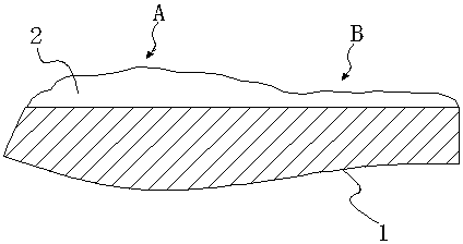
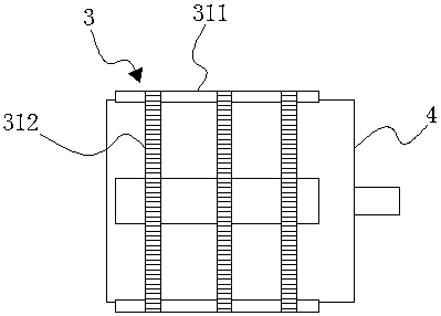
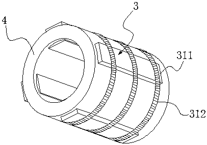
[0038] Embodiment 1: as Figure 2 to Figure 4As shown, a shaft end grinding method is provided with a grinding sleeve 4 with a plurality of elastic grinding blocks 3, a plurality of elastic grinding blocks 3 are connected on the grinding sleeve 4 and a plurality of elastic One end of the grinding block 3 passes through the grinding sleeve 4 and extends into the inside of the grinding sleeve 4 to form a grinding part; when grinding, insert the coated shaft end into the grinding sleeve In the interior of the shaft, a plurality of elastic grinding blocks 3 are elastically in contact with the coating 2 on the shaft end 1, and then the grinding sleeve 4 is rotated to utilize the multiple elastic grinding blocks on the grinding sleeve 4 3 Elastic grinding of the coating 2 on the shaft end 1. Before the shaft end is inserted into the grinding sleeve, each elastic grinding block is in a normal state. After the shaft end is inserted into the grinding sleeve, since the elastic grinding...

Embodiment 2

[0051] Embodiment 2: Compared with Embodiment 1, the difference is: the grinding step is:

[0052] S1, first extend the coated shaft end into the inside of the grinding sleeve;

[0053] S2, placing multiple grinding blocks in multiple limiting grooves;

[0054] S3, then wind the spring one on the outside of the grinding sleeve with multiple grinding blocks, so that the spring one is in contact with the other end of the multiple grinding blocks to elastically compress the multiple grinding blocks on the multiple grinding blocks One end of a plurality of grinding blocks protrudes into the inside of the grinding sleeve to contact the coating on the end of the shaft, and then rotates the grinding sleeve for grinding.

Embodiment 3

[0055] Embodiment 3: as Figure 6 As shown, compared with Embodiment 1, the difference lies in that an arc-shaped inner groove 6 is formed on the upper base of the trapezoidal grinding block 311 . This can increase the contact area with the coating, thereby further improving the grinding quality.


PUM


Abstract

The invention discloses a shaft end grinding method and tool. The shaft end grinding method comprises the steps that a grinding sleeve with a plurality of elastic grinding blocks is arranged, the multiple elastic grinding blocks are connected to the grinding sleeve, and one ends of the multiple elastic grinding blocks penetrate through the grinding sleeve to be inserted into the grinding sleeve; and during grinding, a shaft end sprayed with a coating stretches into the grinding sleeve, thus the multiple elastic grinding blocks elastically make contact with the coating on the shaft end, then the grinding sleeve is rotated, and the coating on the shaft end is elastically ground through the multiple elastic grinding blocks on the grinding sleeve. The shaft end sprayed with the coating can beground, the cylindricity of the ground shaft end is guaranteed, operation is very convenient and quick, the working intensity is lowered, and the working efficiency is improved.

Description

technical field [0001] The invention relates to a grinding method and a grinding tool, in particular to a shaft end grinding method and a grinding tool. Background technique [0002] When a rail vehicle passes through curves and turnouts at high speed or stops on a curve with superelevation, the roll increases significantly, and the load on one side of the wheel is reduced. When encountering strong lateral winds, it may even overturn and become unstable, reducing safety. It is necessary to increase the roll stiffness of the vehicle to limit its roll angle, but it cannot affect the vibration characteristics of the vehicle such as ups and downs, yaw, shake head, telescopic and nod. [0003] At present, when the anti-rolling torsion bar devices of some rail vehicles are overhauled, it is found that the end of the torsion bar shaft is corroded, and many of the anti-rolling torsion bar devices exceed the overhaul standard. Due to the high scrap rate of the anti-rolling torsion b...

Claims


Application Information

Patent Timeline
Patent Type & Authority Applications(China)
IPC IPC(8): B24B5/04B24D5/06B24D5/16B24D99/00
CPCB24B5/04B24D5/06B24D5/16B24D99/005
Inventor 王亚平杜方孟范湘盛超包胜军韩喜龙
Owner ZHUZHOU TIMES NEW MATERIALS TECH
Why Eureka
Try Eureka