

A kind of optical glass automatic edging equipment
Patent Information
- Authority / Receiving Office
- CN · China
- Patent Type
- Patents(China)
- Current Assignee / Owner
- TONGXIANG HESHAN CRAFT GLASSWARE FACTORY
- Publication Date
- 2019-12-03
Smart Images
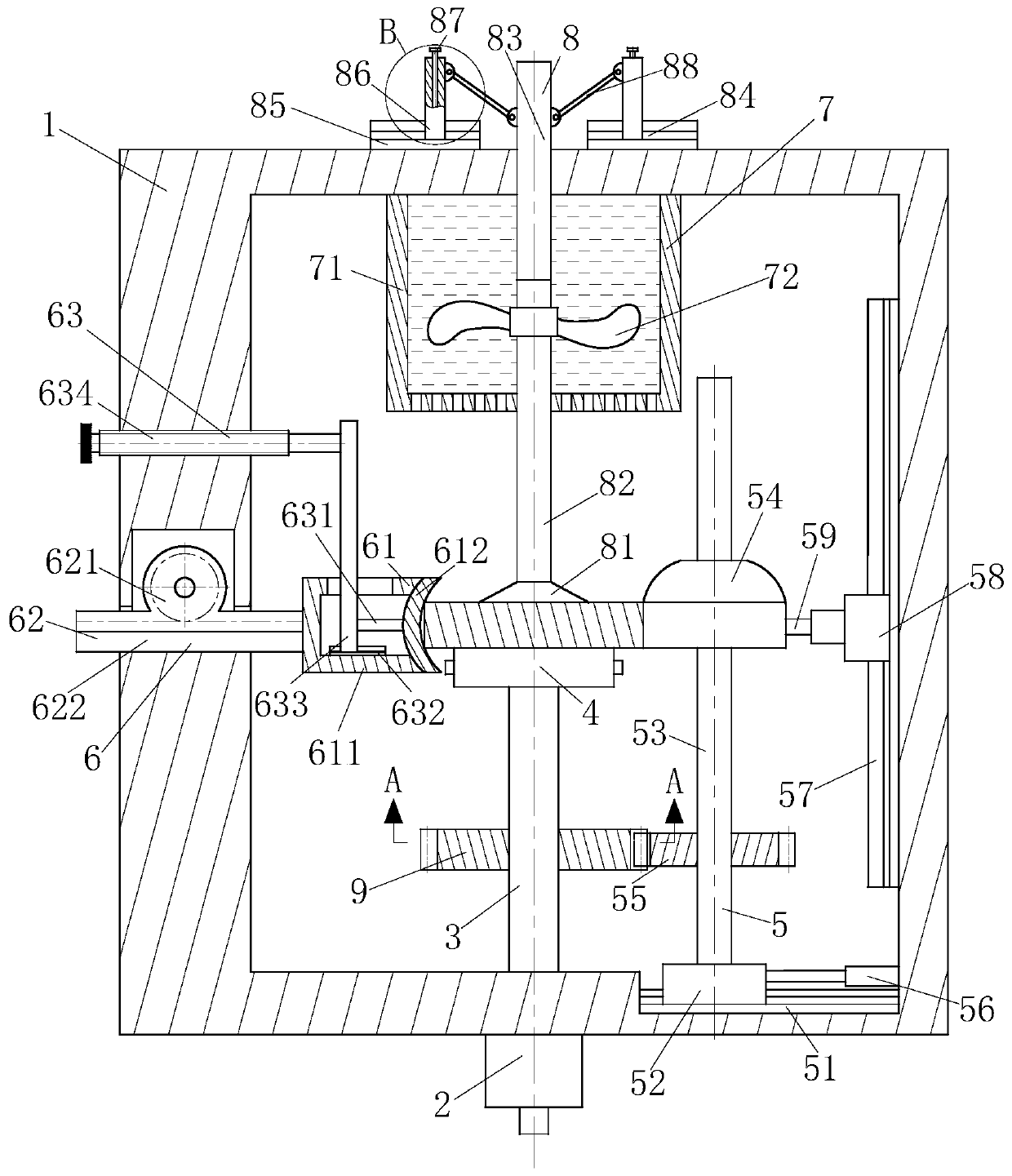
Figure 1 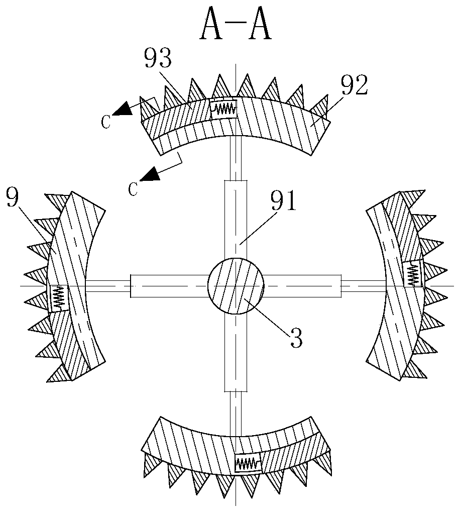
Figure 2 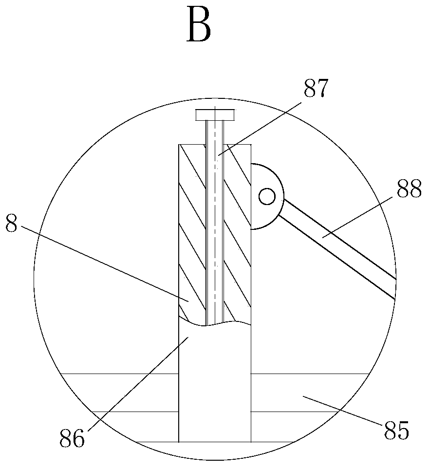
Figure 3
Abstract
Description
technical field
[0001] The invention belongs to the technical field of optical glass production, in particular to an automatic edge grinding equipment for optical glass. Background technique
[0002] Optical glass refers to glass that can change the direction of light propagation and change the relative spectral distribution of ultraviolet, visible or infrared light. Optical glass in the narrow sense refers to colorless optical glass; optical glass in the broad sense also includes colored optical glass, laser glass, quartz optical glass, anti-radiation glass, ultraviolet and infrared optical glass, fiber optic glass, acousto-optic glass, magneto-optical glass and photochromic Glass. Optical glass can be used to manufacture lenses, prisms, mirrors and windows in optical instruments. Components made of optical glass are key elements in optical instruments. Optical glass needs to be cold processed in the process of becoming an optical element, and the edge grinding of optica...