Drill bit grinding device with deflectable steering plate

A technology of grinding device and turning plate, which is applied in the direction of grinding/polishing safety device, machine tool designed for grinding the rotating surface of workpiece, grinding machine, etc., which can solve the problems of low repair success rate, high equipment cost, complicated operation, etc., and achieve The effect of high restoration success rate, low production cost and high safety

Pending Publication Date: 2022-03-01
台山市恒讯研磨科技有限公司
View PDF0 Cites 0 Cited by
  • Summary
  • Abstract
  • Description
  • Claims
  • Application Information

AI Technical Summary

Problems solved by technology

The above tool grinding machines have complex structures, high equipment costs, complicated operations, and high requirements on the skills of the operators. The economic indicators of their use are generally only suitable for processing centers with strong processing capabilities; the above manual grinding can only be performed by experienced fitters. Or other technicians, the grinding quality depends entirely on the experience of the operator, and it is difficult to guarantee the size of the cutting edge, the success rate of repair is low, and there are certain safety risks

Method used


Image

  • Drill bit grinding device with deflectable steering plate
  • Drill bit grinding device with deflectable steering plate
  • Drill bit grinding device with deflectable steering plate

Examples


Embodiment Construction

[0032] In describing the present invention, it should be understood that the terms "center", "longitudinal", "transverse", "upper", "lower", "front", "rear", "left", "right", " The orientations or positional relationships indicated by "vertical", "horizontal", "top", "bottom", "inner" and "outer" are based on the orientations or positional relationships shown in the drawings, and are only for the convenience of describing the present invention and Simplified descriptions, rather than indicating or implying that the device or element referred to must have a particular orientation, be constructed and operate in a particular orientation, and thus should not be construed as limiting the invention. In the description of the present invention, unless otherwise specified, "plurality" means two or more.

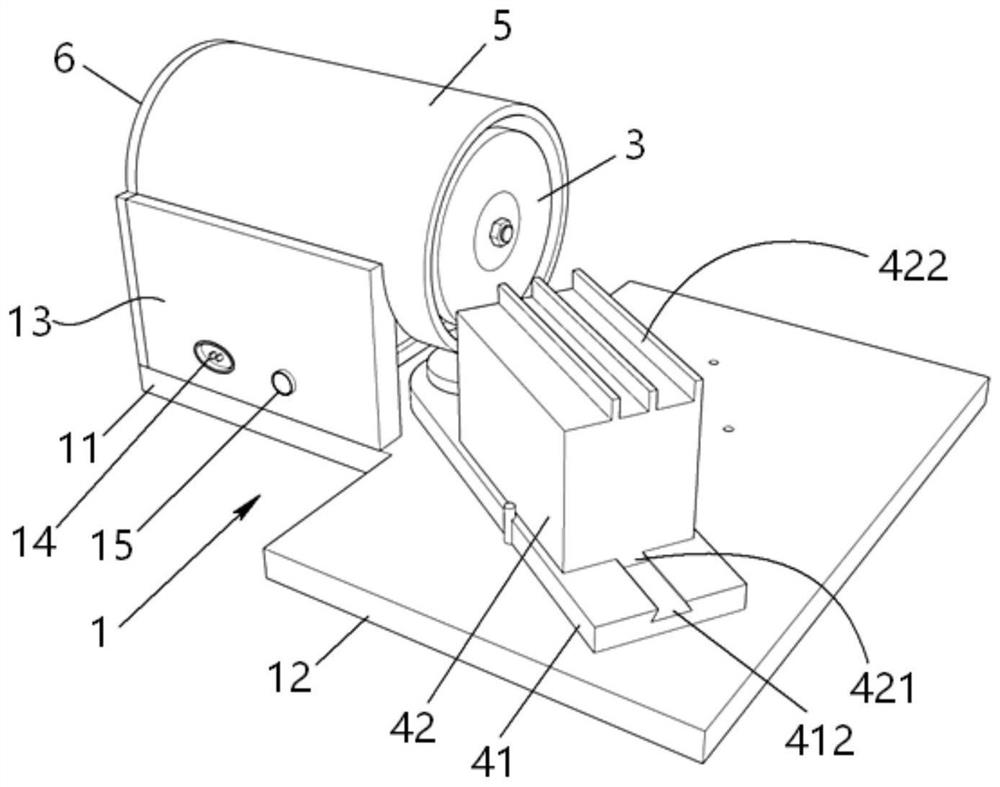
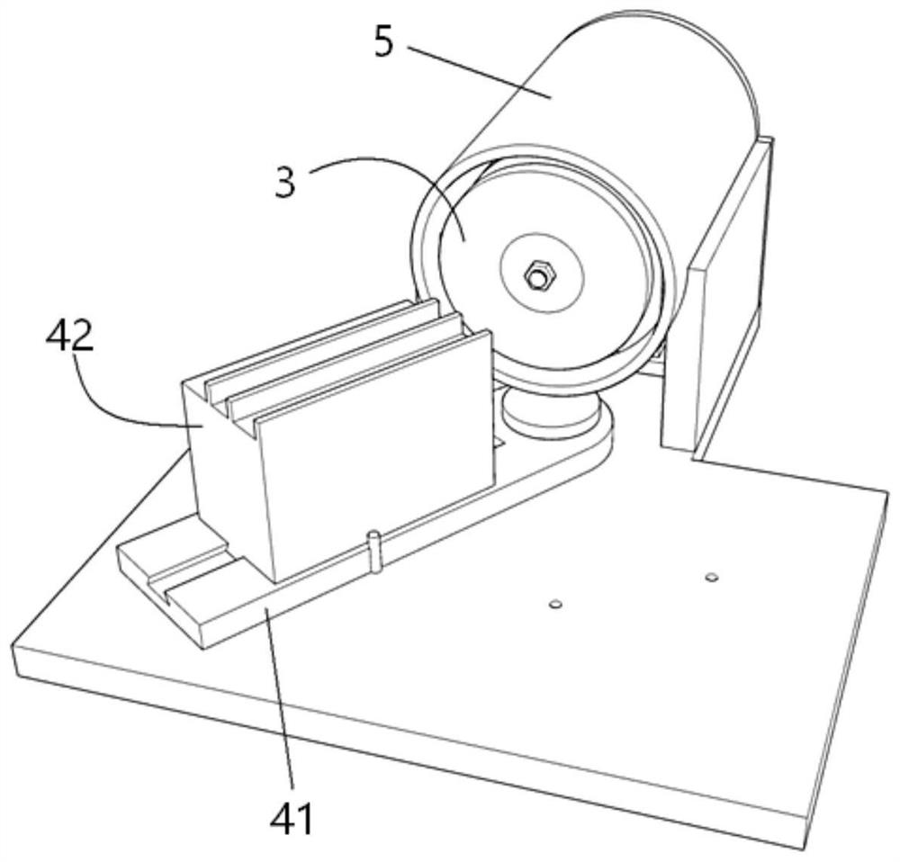
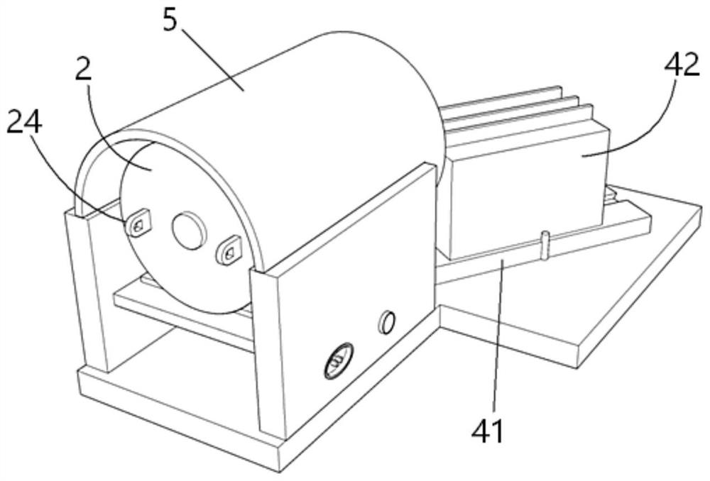
[0033] Please also see Figure 1 to Figure 8 , a kind of drill grinding device with a deflectable steering plate in this case, including a frame 1, a motor 2 mounted on the frame 1,...


PUM


Abstract

A drill bit grinding device with a deflectable steering plate comprises a seat frame, a motor mounted on the seat frame, a grinding wheel mounted on a steering shaft of the motor, and a guide mechanism mounted in front of the grinding wheel. The seat frame comprises a T-shaped bottom plate, the T-shaped bottom plate is provided with a longitudinal plate and a transverse plate, a motor mounting seat is arranged on the longitudinal plate, a turning shaft is arranged on the transverse plate, and four positioning grooves are formed in the position, on the periphery of the turning shaft, of the transverse plate. The motor is fixed on the motor mounting seat through a fixing seat; the fixing base comprises a horizontal plate and a vertical plate, a runway-shaped shaft hole is formed in the vertical plate, and a rotating shaft of the motor penetrates through the runway-shaped shaft hole. And the grinding wheel is fastened on a rotating shaft of the motor through a nut. And the guide mechanism comprises a steering plate and a sliding seat on the steering plate, the steering plate is rotationally mounted on the steering shaft, a dovetail convex block is arranged at the bottom of the sliding seat and matched with a dovetail groove in the steering plate, and a plurality of guide plates are arranged on the top surface of the sliding seat side by side at intervals. The device is simple in structure, good in applicability and high in drill bit grinding success rate.

Description

technical field [0001] The invention relates to the field of grinding equipment manufacture, in particular to a drill bit grinding device with a deflectable steering plate. Background technique [0002] During the entire life cycle of the drill bit used in the machining field, it is generally necessary to grind the cutting edge multiple times, so that it can ensure high processing efficiency, obtain the required size and surface roughness during the drilling process. degree of hole etc. In the prior art, the grinding of the drill bit edge is generally completed in the following two ways: using a special tool grinder, manual grinding, and grinding. The above tool grinding machines have complex structures, high equipment costs, complicated operations, and high requirements on the skills of the operators. The economic indicators of their use are generally only suitable for processing centers with strong processing capabilities; the above manual grinding can only be performed b...

Claims


Application Information

Patent Timeline
IPC IPC(8): B24B3/24B24B5/35B24B55/00B24B41/02
CPCB24B3/24B24B5/35B24B55/00B24B41/02
Inventor 颜杰钦
Owner 台山市恒讯研磨科技有限公司
Why Eureka
Try Eureka