
Numerical control deburring system and deburring method

A technology for deburring and controlling cabinets, which is applied in the direction of large fixed members, clamping, supporting, etc., can solve the problems of high equipment cost, high labor cost, and damage to workpieces, and achieve the effect of easy operation, efficiency, and low cost

Pending Publication Date: 2018-11-06
陕西大中科技发展有限公司
View PDF0 Cites 3 Cited by
  • Summary
  • Abstract
  • Description
  • Claims
  • Application Information

AI Technical Summary

Problems solved by technology

The efficiency of manual deburring is low and the labor cost is high; the vicinity of the burrs of electrolytic deburring parts is also subjected to electrolysis, the surface will lose its original luster, and even affect the dimensional accuracy; ultrasonic deburring is mainly for some microscopic burrs, generally if the burrs need If you use a microscope to observe, you can try to use ultrasonic methods to remove
For burrs visible to the naked eye, it mainly depends on the strength of the bond. Ultrasonic waves can be used for burrs with weak bond strength. Generally, if the burrs can only be processed with a knife, the ultrasonic method is not good; use high-pressure water spray to remove burrs. If the pressure is insufficient, The effect of deburring cannot be achieved. Although the pressure is too high, the burrs can be removed, but there is a danger of damage to the workpiece. The fit between the nozzle and the valve body is not ideal. high

Method used


Image

  • Numerical control deburring system and deburring method
  • Numerical control deburring system and deburring method
  • Numerical control deburring system and deburring method

Examples


Embodiment Construction

[0030] The numerical control deburring system and deburring method of the present invention will be described in detail below with reference to the drawings and embodiments.

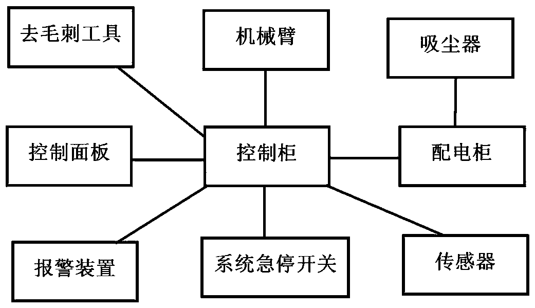
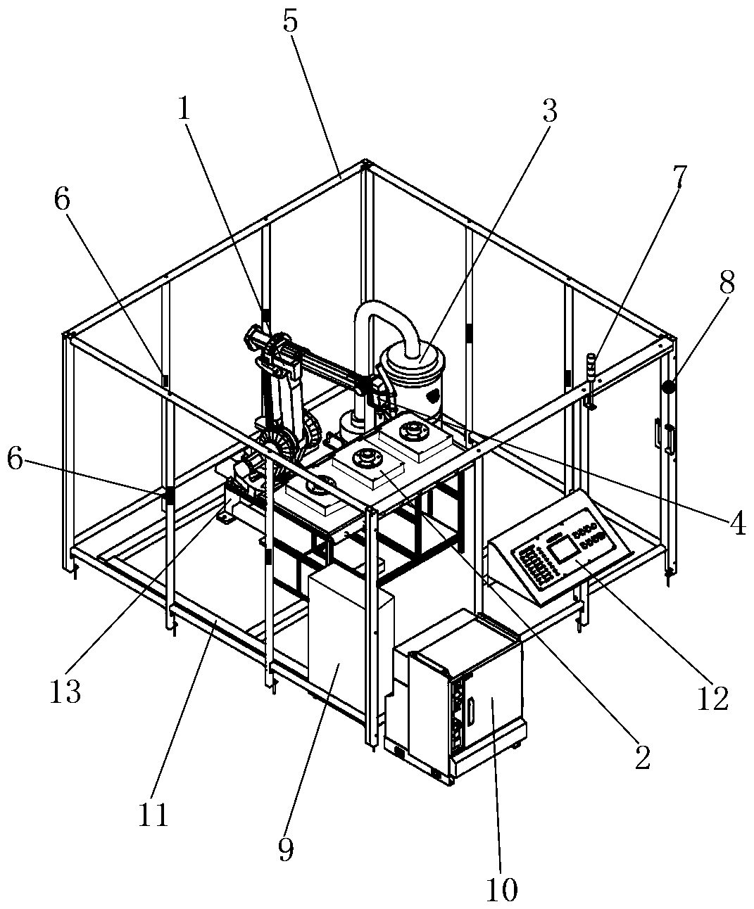
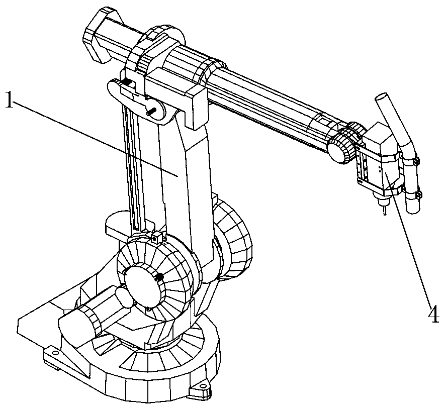
[0031] The numerical control deburring system of the present invention, such as figure 1 , figure 2 As shown, it includes a manipulator 1, a workbench 2, a safety fence 5, a power distribution cabinet 9, a control cabinet 10, and a control panel 12. The manipulator 1 and the workbench 2 are both set in the safety fence 5, and the workbench 2 is set Directly below the front end of the manipulator 1; the power distribution cabinet 9 is installed in the fence; the control panel 12 is installed on the fence; the control cabinet 10 is installed outside the fence; the power distribution cabinet 9 and the control panel 12 are both The control cabinet 10 is electrically connected through cables; the manipulator 1 is connected to the power distribution cabinet 9 through the control cabinet 10 by cables; the manipula...


PUM


Abstract

The invention discloses a numerical control deburring system and deburring method and belongs to the field of numerical control machinery. The numerical control deburring system is characterized by comprising a manipulator, a workbench, a safety rail, a power distribution cabinet, a control cabinet and a control panel; the manipulator and the workbench are both arranged in the safety rail; the control panel is arranged on the rail; the power distribution cabinet and the control panel are both in electric connection with the control cabinet through cables; the manipulator passes through the control cabinet to be connected with the power distribution cabinet through a cable; and a deburring tool is arranged at the front end of the manipulator passes through the control cabinet to be in electric connection with the power distribution cabinet through a cable. A practical machining unit comprises the manipulator, the deburring tool, the workbench, a dust collector, the safety rail and support equipment and is achieved by being combined with a deburring process, deburring machining of any-shape parts can be completed, a safety guarantee is provided through the safety rail, a warning device and a system emergency stop switch, thus the practical training and machining process is safe and reliable, and the safe and reliable deburring system which is low in cost and easy to operate is provided for practical training.

Description

Technical field [0001] The invention belongs to the field of numerical control machinery, and in particular relates to a numerical control deburring system and a deburring method for practical training demonstration. Background technique [0002] The machining methods of mechanical parts can be roughly divided into material removal processing, deformation processing, and additional processing. In all kinds of processing, the extra parts derived from the processed parts that do not match the required shape and size are burrs. The occurrence of burrs varies with the processing method. [0003] The existence of burrs will cause the entire mechanical system to fail to work normally, reducing reliability and stability. When the machine with burrs performs mechanical movement or vibration, the burr will cause premature wear on the sliding surface of the machine, increase in noise, and even cause the mechanism to jam and malfunction; some electrical systems will suffer from burrs when m...

Claims


Application Information

Patent Timeline
IPC IPC(8): B25J11/00B23Q1/00B23Q3/06B23Q11/00B23Q11/08
CPCB23Q1/0045B23Q3/06B23Q11/0046B23Q11/08B25J11/006
Inventor 王天平吴伟王大为曹喆周辉汪伟
Owner 陕西大中科技发展有限公司
Learn More