
A CSTR fermentation tank discharge system and process for mixing multiple raw materials

A discharge system and fermenter technology, which is applied to specific-purpose bioreactor/fermenter, bioreactor/fermenter combination, biomass post-treatment, etc., can solve the problem of overflow pipes and sludge discharge pipes being damaged by fibers and Problems such as clogging of crystalline substances, inability to achieve gravity sludge discharge, inability to apply CSTR fermentation tanks, etc.

Active Publication Date: 2021-09-14
JIANGXI ZHENGHE ENVIRONMENTAL PROTECTION ENG CO LTD
View PDF4 Cites 0 Cited by
  • Summary
  • Abstract
  • Description
  • Claims
  • Application Information

AI Technical Summary

Problems solved by technology

[0003] For the fermentation of mixed raw materials (the raw materials are mainly straw and livestock and poultry manure), due to the high content of cellulose, hemicellulose and lignin in the straw, the conventional unpowered discharge and sludge discharge system will easily lead to overflow pipes and sludge discharge. The pipeline is blocked by fibers and crystalline substances; and the overall fermentation concentration of the mixed raw materials is high, and the elevation difference of the tank itself often cannot realize gravity sludge discharge
[0004] Therefore, the current CSTR anaerobic fermentation tank discharge system cannot be applied to the CSTR fermentation tank discharge of multi-material mixed fermentation; in addition, the current development trend of biogas projects is large-scale development, no longer a single tank for fermentation, large-scale development There are more and more anaerobic fermentation tanks in a biogas engineering project. If the unified control of multiple tanks can be realized, the advantages of scale can be fully utilized

Method used


Image

  • A CSTR fermentation tank discharge system and process for mixing multiple raw materials

Examples


Embodiment approach

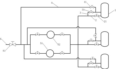
[0024] Multiple CSTR fermenter 1 sludge discharge systems are connected together and connected to the sludge discharge power system. The sludge discharge power system in this embodiment is a screw pump, and the number of screw pumps is usually a plurality of parallel layouts. Calculate the number of screw pumps according to the total anaerobic volume and fermentation time of multiple CSTR fermenters 1. Preferably, the number of screw pumps can be arranged according to the mode of dual use and one standby. As a typical implementation, this embodiment is described according to the layout of two screw pumps, which are respectively the first screw pump 51 and the second screw pump 52. The upstream and downstream of each screw pump have valves respectively, which can control the screw pump. Power direction is controlled.

[0025] Each CSTR fermentation tank 1 has a return pipe 4, the end of the return pipe 4 is connected to the downstream of the screw pump and realizes the connecti...


PUM


Abstract

A CSTR fermentation tank discharge system with multiple raw materials mixed, comprising a CSTR fermentation tank, a sludge discharge pipe, a discharge pipe, a return pipe, a sludge discharge power system and a discharge pipe. Among them, there are multiple CSTR fermentation tanks, each CSTR fermentation tank has a mud discharge pipe, a discharge pipe and a return pipe, each mud discharge pipe has a mud discharge valve, each discharge pipe has a discharge valve, each return pipe With a backflow valve, the end of the sludge discharge pipe and the discharge pipe of each CSTR fermenter are connected together to realize the combination of the discharge and sludge discharge systems and realize time-sharing control. Multiple CSTR fermentation tank sludge discharge systems are connected together and connected to the sludge discharge power system. The discharge pipe of the entire anaerobic fermentation discharge system is located at the end of the discharge system, and correspondingly, the discharge pipe also has a discharge valve to realize discharge control. At the same time, the present invention also provides a discharge process using the above-mentioned CSTR fermenter discharge system mixed with multiple raw materials.

Description

technical field [0001] The invention relates to the technical field of anaerobic fermentation, in particular to a CSTR fermenter discharge system and process for mixing multiple raw materials. Background technique [0002] Conventional CSTR anaerobic fermentation tanks usually adopt the overflow discharge system formed by feeding in from the bottom up, and the gravity sludge discharge system formed by the elevation difference of the tank itself, which is operated separately, to maintain the normal operation of the CSTR anaerobic fermentation tank and ensure There is no material deposition or hardening inside the tank. [0003] For the fermentation of mixed raw materials (the raw materials are mainly straw and livestock and poultry manure), due to the high content of cellulose, hemicellulose and lignin in the straw, the conventional unpowered discharge and sludge discharge system will easily lead to overflow pipes and sludge discharge. The pipeline is blocked by fibers and c...

Claims


Application Information

Patent Timeline
Patent Type & Authority Patents(China)
IPC IPC(8): C12M1/36C12M1/00
CPCC12M41/00C12M41/44C12M41/48
Inventor 龚贵金黄强
Owner JIANGXI ZHENGHE ENVIRONMENTAL PROTECTION ENG CO LTD
Learn More