
Garment shearing machine cloth negative pressure clamping device

A technology of a clamping device and a cutting machine, which is applied in the cutting of textile materials, textiles and papermaking, etc., can solve the problems of difficulty in ensuring that the fabric is completely flat, affecting the work efficiency of staff, and discarding clothing, etc. Air leakage, simple principle effect

Inactive Publication Date: 2018-11-06
安徽美裕集团有限公司
View PDF0 Cites 3 Cited by
  • Summary
  • Abstract
  • Description
  • Claims
  • Application Information

AI Technical Summary

Problems solved by technology

[0002] In the garment processing process, the most steps are cutting and sewing. The staff puts the prepared fabric on the workbench for operation, but the fabric needs to be fixed, and pressing it with heavy objects will inevitably bring inconvenience to the operation and affect the safety of the staff. work efficiency, and it is difficult to ensure that the whole piece of fabric is completely flat, which may easily cause garment scrapping. Therefore, we propose a fabric negative pressure clamping device for garment cutting machine to solve the above problems

Method used

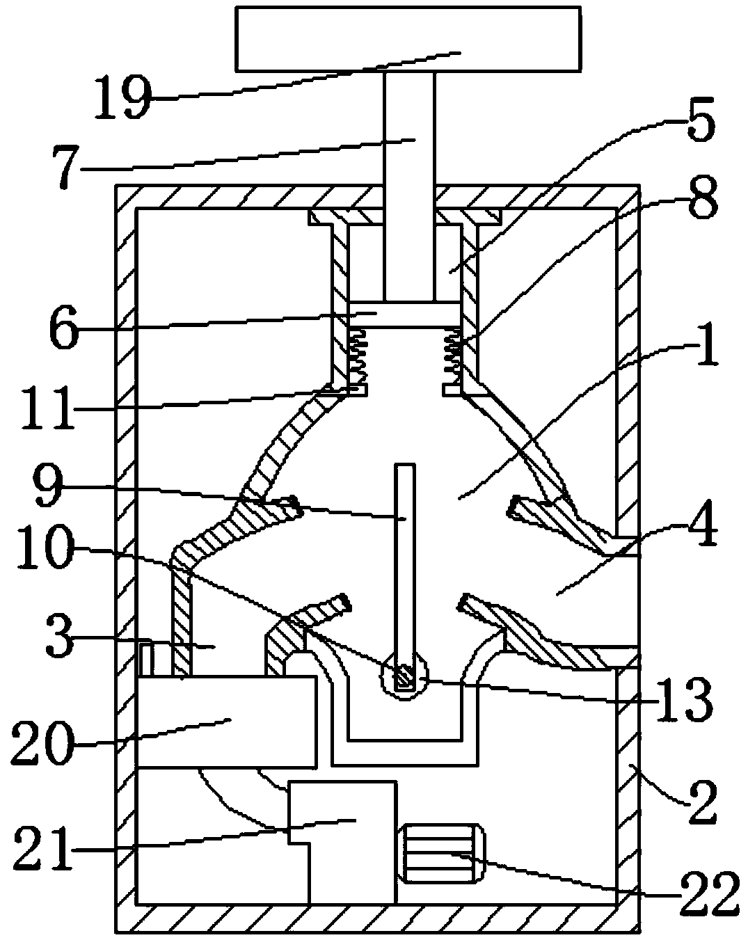
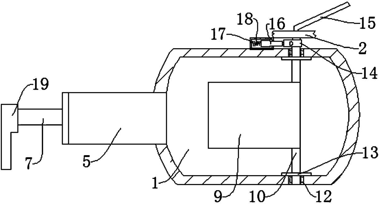

Image

  • Garment shearing machine cloth negative pressure clamping device
  • Garment shearing machine cloth negative pressure clamping device
  • Garment shearing machine cloth negative pressure clamping device

Examples


Embodiment Construction

[0016] The following will clearly and completely describe the technical solutions in the embodiments of the present invention with reference to the accompanying drawings in the embodiments of the present invention. Obviously, the described embodiments are only some, not all, embodiments of the present invention. Based on the embodiments of the present invention, all other embodiments obtained by persons of ordinary skill in the art without making creative efforts belong to the protection scope of the present invention.

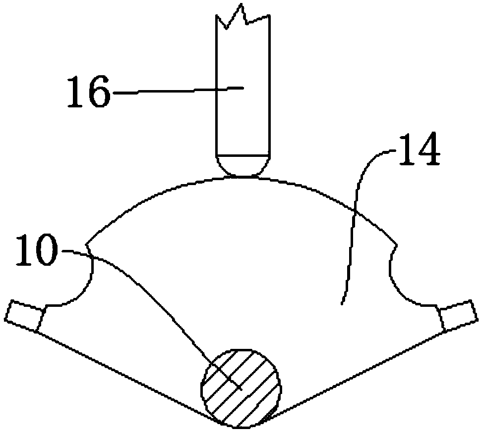
[0017] see Figure 1-2 , the present invention provides a technical solution: a fabric negative pressure clamping device for a garment cutting machine, comprising a casing 2, a working chamber 1 is provided inside the casing 2, and a first branch pipe 3, a second branch pipe 4 and a first branch pipe 4 are connected to the working chamber 1. Compression chamber 5, a piston 6 is arranged inside the compression chamber 5, and a pull rod 7 is connected to the pis...


PUM


Abstract

The invention discloses a garment shearing machine cloth negative pressure clamping device, which comprises a case, wherein a work cavity is arranged inside the case. The garment shearing machine cloth negative pressure clamping device is characterized in that the cloth is clamped by using the negative pressure piston pulling principle; a device main body uses a first branch pipe, a second branchpipe and a work cavity for matching with a compression cavity for operation; through controlling the communication of the compression cavity with the first branch pipe or the second branch pipe, the movement mode of a piston inside the compression cavity is realized; when the pressure intensity inside the compression cavity is reduced, the piston can pull a pull rod to drive the press plate to move the work cavity; the spring is compressed; next, the press plate and the operation table are matched; the cloth can be fixed; when the pressure intensity inside the compression cavity starts to increase, the spring can extend; the spring an push the piston to a direction leaving far away from the work cavity; the extrusion of the press plate on the cloth can be relieved; an air extraction machine aims at completely extracting the air inside the compression cavity to make the negative pressure state; the rubber ring can be matched with the movable baffle plate; the air leakage is prevented; the structure and the principle are simple; the popularization and the use are facilitated.

Description

technical field [0001] The invention relates to the technical field of mechanical equipment, in particular to a fabric negative pressure clamping device for a garment cutting machine. Background technique [0002] In the garment processing process, the most steps are cutting and sewing. The staff puts the prepared fabric on the workbench for operation, but the fabric needs to be fixed, and pressing it with heavy objects will inevitably bring inconvenience to the operation and affect the safety of the staff. work efficiency, and it is difficult to ensure that the whole piece of fabric is completely flat, and it is easy to cause the garment to be scrapped. Therefore, we propose a fabric negative pressure clamping device for garment cutting machine to solve the above problems. Contents of the invention [0003] The object of the present invention is to provide a fabric negative pressure clamping device for a garment cutting machine to solve the problems raised in the above-me...

Claims


Application Information

Patent Timeline
Patent Type & Authority Applications(China)
IPC IPC(8): D06H7/00
CPCD06H7/00
Inventor 余晓怀
Owner 安徽美裕集团有限公司
Learn More