Closed dehumidification water-water heat pump drying system with multiple drying rooms

A drying system and water heating technology, applied in the field of drying system, can solve problems such as failure to meet process requirements, poor quality of dried materials, and increased energy consumption of the unit, so as to reduce initial investment costs, reduce labor intensity, and improve The effect of finished product quality

Inactive Publication Date: 2018-11-06
江苏必领能源科技有限公司
View PDF9 Cites 1 Cited by
  • Summary
  • Abstract
  • Description
  • Claims
  • Application Information

AI Technical Summary

Problems solved by technology

The disadvantage of this dehumidification method is: when the outdoor environment is humid, the difference between the humidity content of the indoor air and the outdoor air becomes smaller, and the required fresh air volume increases, resulting in an increase in the energy consumption of the unit; even the ambient humidity is particularly high When the fresh air volume is added to the maximum, the humidity in the drying room still cannot meet the process requirements, resulting in the deterioration of the quality of the dried material
For the number of drying rooms at the drying point is more than 20, since each drying room uses the same air source heat pump, the initial investment cost is relatively high

Method used


Image

  • Closed dehumidification water-water heat pump drying system with multiple drying rooms

Examples


Embodiment

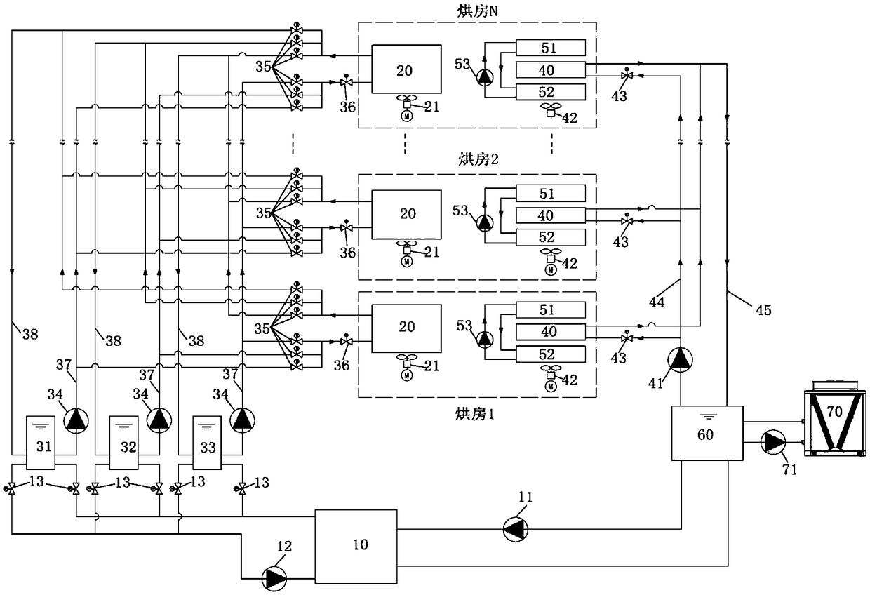
[0022] Example: such as figure 1 As shown, a closed dehumidification water-water heat pump multi-drying room drying system includes a water-water heat pump 10, a hot water tank, an energy storage water tank 60 and several drying rooms, each of which is provided with a heating coil 20, Heating axial flow fan 21, dehumidification coil 40 and dehumidification fan 42, the heating axial flow fan 21 is used to drive the air to be heated through the heating coil 20, and the dehumidification fan 42 is used to drive the air to pass through the dehumidification coil 40 for dehumidification, so The hot water generated by the water-to-water heat pump 10 enters the hot water tank through the pipeline, and the hot water on one side of the hot water tank is pumped into the heating coil 20 by the heating water pump 34 through the heating water pipeline 37, and the hot water passes through the heating coil 20 After heat exchange, return to the hot water tank through the first return water pipe...


PUM


Abstract

The invention relates to a closed dehumidification water-water heat pump drying system with multiple drying rooms. The closed dehumidification water-water heat pump drying system comprises a water-water heat pump, a hot water tank, an energy storage water tank and a plurality of drying rooms. A heating coil, a heating axial flow fan, a dehumidification coil and a dehumidification fan are arrangedin each drying room. Hot water generated by the water-water heat pump enters the hot water tank through a pipeline, the hot water in the hot water tank is pumped into each heating coil by a heating water pump through a heating water pipeline, and the hot water conducts heat exchange through the heating coil and then returns to the hot water tank through a first water return pipeline. The water inthe hot water tank enters the water-water heat pump through a water pump on a condensation side. Chilled water generated by the water-water heat pump enters the energy storage water tank through a pipeline. The cold water in the energy storage water tank is pumped into each dehumidification coil by a dehumidification water pump through a dehumidification pipeline, and the cold water conducts heatexchange through the dehumidification coil and then returns to the energy storage water tank through a second water return pipeline. The cold water in the energy storage water tank enters the water-water heat pump through a water pump on an evaporation side. The system saves energy, is environmentally friendly and has high drying quality.

Description

technical field [0001] The invention relates to a drying system, in particular to a closed dehumidification water-water heat pump drying system with multiple drying rooms. Background technique [0002] At present, the main method of drying tobacco, traditional Chinese medicine, wood and crops is to use coal-fired heating. Due to its pollution, coal-fired heating is increasingly restricted, and it is imperative to replace coal-fired heating. The air source heat pump system is an ideal way to replace coal-fired heating due to its characteristics of no emission pollution and simple system. At present, the evaporator of the air source heat pump system is a finned heat exchanger, and its heat extraction method is to extract heat from the environment, which causes the efficiency of the unit to be greatly affected by the ambient temperature. Especially in northern China, when the ambient temperature is low, the COP of the unit is low, which makes the operation energy consumption o...

Claims


Application Information

Patent Timeline
Patent Type & Authority Applications(China)
IPC IPC(8): F26B9/02F26B23/00
CPCF26B9/02F26B23/005
Inventor 郑接林姚峻胡易木
Owner 江苏必领能源科技有限公司
Why Eureka
Try Eureka