
Flame-adjustable burner, and installation structure and application method thereof

A burner and burner nozzle technology are applied in the field of adjustable flame burners and their installation structures, which can solve the problems of incomplete combustion, large temperature difference in the kiln, unadjustable flame, etc., achieve low-nitrogen combustion, improve kiln head Effect of temperature and shortening of travel stroke

Pending Publication Date: 2018-11-06
SINOSTEEL ANSHAN RES INST OF THERMO ENERGY CO LTD
View PDF6 Cites 0 Cited by
  • Summary
  • Abstract
  • Description
  • Claims
  • Application Information

AI Technical Summary

Problems solved by technology

At present, most of the domestic gas-fired rotary kiln burners are lagging behind in terms of performance indicators and control levels. The main performance is that manual ignition is adopted, and there is no automatic control of air-fuel ratio, resulting in large temperature differences in the kiln and poor quality of calcined products; and The traditional gas-fired burner has a small adjustment ratio, the flame cannot be adjusted, and there are defects such as uneven gas mixing, incomplete combustion, and unsafety.
In addition, the burner is fixed on the kiln hood, its inclination angle is fixed, and there is no room for adjustment. The performance and effect of the burner have been finalized after the design and installation are completed, and cannot be optimized through post-installation adjustments; if using It is found that the flame directly washes the kiln lining, so it can only be reinstalled after disassembly

Method used


Image

  • Flame-adjustable burner, and installation structure and application method thereof
  • Flame-adjustable burner, and installation structure and application method thereof
  • Flame-adjustable burner, and installation structure and application method thereof

Examples


Embodiment Construction

[0033] The specific embodiment of the present invention will be further described below in conjunction with accompanying drawing:

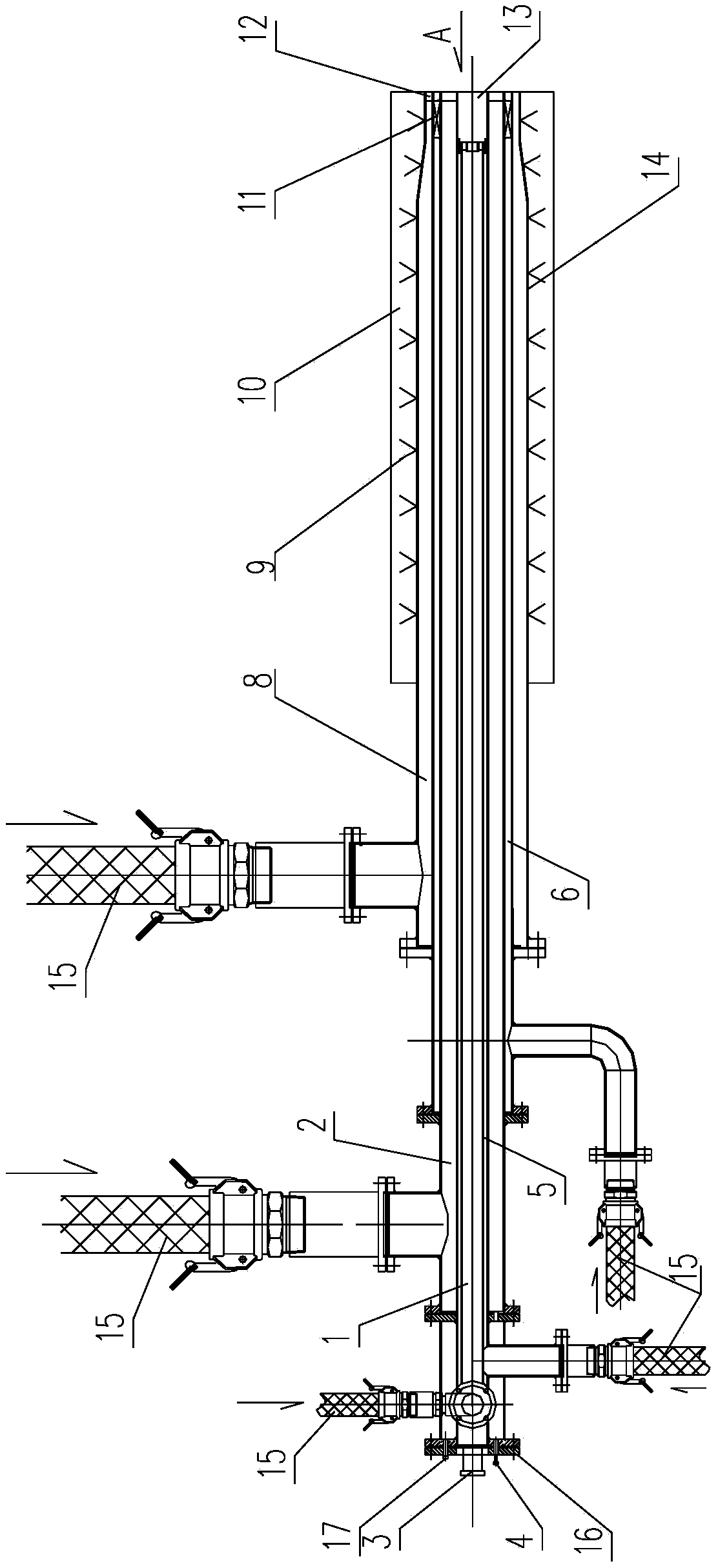
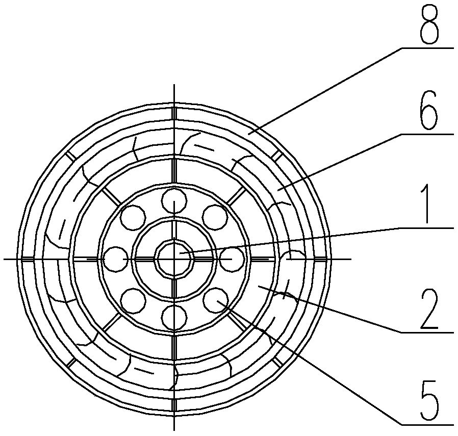
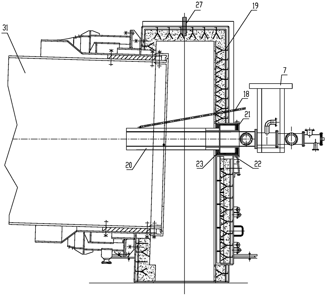
[0034] Such as figure 1 As shown, an adjustable flame burner according to the present invention includes a burner body 20, air pipes and gas pipes connected to the burner body 20, and flow measurement and adjustment devices arranged on each air pipe and gas pipe; The burner body 20 is provided with a central air channel 1, an inner ring gas channel 5, an inner ring air channel 2, an outer ring gas channel 6 and an outer ring air channel 8 from the inside to the outside; the front end of the burner body 20 is a burner Nozzle; the inner ring gas channel 5 and the central air channel 1 are indented for a certain distance at the burner nozzle, and the space between the end faces of the inner ring gas channel 5 and the central air channel 1 and the end face of the burner nozzle forms a mixed deflagration chamber 13 ; The outer ring air duct 8 is provi...


PUM


Abstract

The invention relates to a flame-adjustable burner, and an installation structure and an application method thereof. The flame-adjustable burner comprises a burner body, air pipes, gas pipes and flowmeasuring and adjusting devices, wherein the air pipes and the gas pipes are connected with the burner body; the flow measuring and adjusting devices are arranged on the air pipes and the gas pipes. The burner body is provided with a center air duct, an inner ring gas duct, an inner ring air duct, an outer ring gas duct and an outer ring air duct from inside to outside in sequence. The flame-adjustable burner provided by the invention is adjustable in flame length, contour and air-fuel ratio. Gas and distributed air can be uniformly and completely mixed. While the calcinations temperature is satisfied, and low-NOx emission can be realized; moreover, the flame-adjustable burner is capable of being automatically adjusted, safe and controllable in the burning process. The flame-adjustable burner has two working positions and can meet the requirements for normal operation and ignition, realize angle fine adjustment through a flexible seal and ensure that flames do not sweep a kiln liner.

Description

technical field [0001] The invention relates to a burner, in particular to an adjustable flame burner used in a rotary kiln, its installation structure and usage method. Background technique [0002] Rotary kilns are widely used in metallurgy, chemical industry, building materials and other fields, and the burner is the core component of the rotary kiln. At present, most of the burners of gas-fired rotary kilns in China are lagging behind in terms of performance indicators and control levels. The main performance is that manual ignition is adopted, and there is no automatic control of air-fuel ratio, resulting in large temperature differences in the kiln and poor quality of calcined products; and The traditional gas-burning burner has a small adjustment ratio, the flame cannot be adjusted, and there are defects such as uneven gas mixing, incomplete combustion, and unsafety. In addition, the burner is fixed on the kiln hood, its inclination angle is fixed, and there is no ro...

Claims


Application Information

Patent Timeline
Patent Type & Authority Applications(China)
IPC IPC(8): F27B7/34F27B7/42
CPCF27B7/34F27B7/42
Inventor 毕仕辉赵春竹胡永贵贾丽娣张世煜王涛
Owner SINOSTEEL ANSHAN RES INST OF THERMO ENERGY CO LTD
Learn More