Method and device for controlling decoupling guidance of rotary missile

A decoupling and missile technology, applied to self-propelled missiles, offensive equipment, instruments, etc., can solve problems such as difficult control, strong coupling of yaw and pitch channels, etc., to improve response, improve ballistic control parameters, and reduce coupling relationship Effect

Pending Publication Date: 2018-11-06
孙宏宇
View PDF0 Cites 9 Cited by
  • Summary
  • Abstract
  • Description
  • Claims
  • Application Information

AI Technical Summary

Problems solved by technology

[0003] In order to overcome the deficiencies of the above-mentioned prior art, the object of the present invention is to provide a method and device for decoupling guidance control of rotating missiles, so as to solve the problems of strong coupling and difficult control of yaw and pitch channels in the existing guidance control technology of rotating missiles

Method used


Image

  • Method and device for controlling decoupling guidance of rotary missile
  • Method and device for controlling decoupling guidance of rotary missile
  • Method and device for controlling decoupling guidance of rotary missile

Examples


Embodiment 1

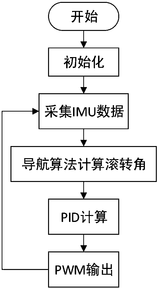
[0050] A method for decoupling guidance and control of a rotating missile, the specific implementation includes the following steps:

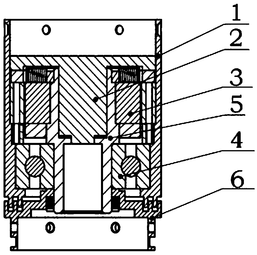
[0051] Step 1, add a derotation cabin between the front cabin and the rear cabin of the rotating missile, the derotation cabin, the physical picture is as follows Figure 4 shown;

[0052] Step 2, install the inertial measurement unit in the front compartment of the rotating missile, so that the sensitive axes of the accelerometer and the gyroscope of the inertial measurement unit are parallel to the respective axes of the rotating missile;

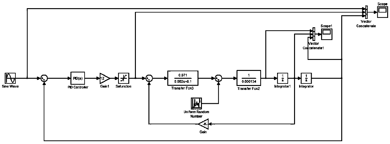
[0053] Step 3, modeling and simulating the derotation cabin section to obtain the proportional, integral and differential parameters used by the PID controller that meets the requirements. figure 2 yes Figure 4 The control model established in the middle racemation section adopts the unit negative feedback model. In the model, the transfer function between the motor torque and voltage is G1, the transf...


PUM


Abstract

The invention discloses a method for controlling the decoupling guidance of a rotary missile. The method comprises the following steps that 1) a racemization cabin section is arranged between the front cabin section and the rear cabin section of the rotary missile; 2) an inertia measuring element is installed in the front cabin section, so that an accelerometer of the inertial measurement elementand the sensitive axis of a gyroscope are parallel to each axis of the front cabin section of the rotary missile; 3) the three-axis angular velocity data and the acceleration data output by the inertia measuring element are collected and calculated through a control plate, and a rolling angle value coupled to the front cabin end is obtained; and 4) a motor in the racemization cabin section is controlled by calculating the difference between the rolling angle of the front cabin section and the set rolling angle, so that coupling among three channels namely, the yaw, pitching and rolling-rotation is reduced to the minimum, wherein the racemization cabin comprises a shell, a motor and a bearing are arranged inside the shell, shafts are arranged inside the motor and the bearing, slip rings arearranged inside the shafts, and one ends of the shafts are provided with structural connecting ports of the rear cabin section. And therefore, the problems that coupling of the yaw and pitching channels is strong in the existing rotary missile guidance, and the control is difficult are solved.

Description

technical field [0001] The invention belongs to the technical field of guidance and control of rotating missiles, and in particular relates to a method and device for decoupling guidance and control of rotating missiles. Background technique [0002] With the transformation of the mode of modern warfare, the core requirement for weapons and equipment has changed to the precision strike capability of weapons. How to improve its strike precision has become the frontier and hot spot of domestic and foreign research. As a low-cost, high-precision modification scheme that is more suitable for conventional ammunition, the rotary bomb is used. The rotation scheme of the rotating missile has unique advantages. For example, it can reduce the impact on the trajectory of the launch asymmetry, structural asymmetry, and engine thrust eccentricity. At the same time, some unavoidable problems also appeared, such as the inertial cross-linking induced by the gyro effect, the control cross-...

Claims


Application Information

Patent Timeline
Patent Type & Authority Applications(China)
IPC IPC(8): F42B15/01G06F17/50
CPCF42B15/01G06F30/20
Inventor 孙宏宇
Owner 孙宏宇
Why Eureka
Try Eureka