Blazed grating based beam deflection angle amplifying unit

A technology of blazed grating and amplifying unit, which is applied in the direction of adopting optical devices, instruments, measuring devices, etc., can solve problems such as lack, and achieve the effect of improving angle measurement accuracy and simple overall structure

Active Publication Date: 2018-11-06
HUAZHONG UNIV OF SCI & TECH
View PDF2 Cites 8 Cited by
  • Summary
  • Abstract
  • Description
  • Claims
  • Application Information

AI Technical Summary

Problems solved by technology

[0004] Aiming at the defects of the prior art, the purpose of the present invention is to solve the exi

Method used


Image

  • Blazed grating based beam deflection angle amplifying unit
  • Blazed grating based beam deflection angle amplifying unit
  • Blazed grating based beam deflection angle amplifying unit

Examples


Embodiment 1

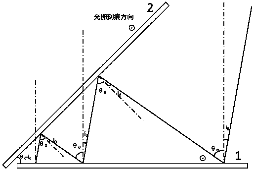
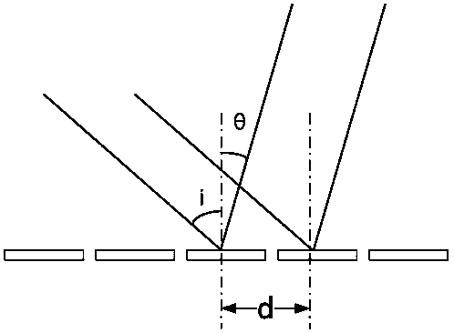
[0050] Two blazed gratings with a blaze angle of 28°41′ and 600 lines per millimeter constitute a subunit, and the wavelength of the incident light is 1.6 μm. If a beam of light is vertically incident on the grating 1, the first order can be obtained by using the grating equation The diffraction angle is 1.287002218rad, accounting for most of the energy, the angle between grating 2 and grating 1 is 1.287002218rad, refer to figure 1 , then the diffracted light is vertically incident on the grating 2, and the diffracted light after passing through the second grating is vertically incident on the grating 1, that is, when the direction of the incident light is near the vertical line of the grating 1, multiple diffractions of light between the two gratings can be ensured.

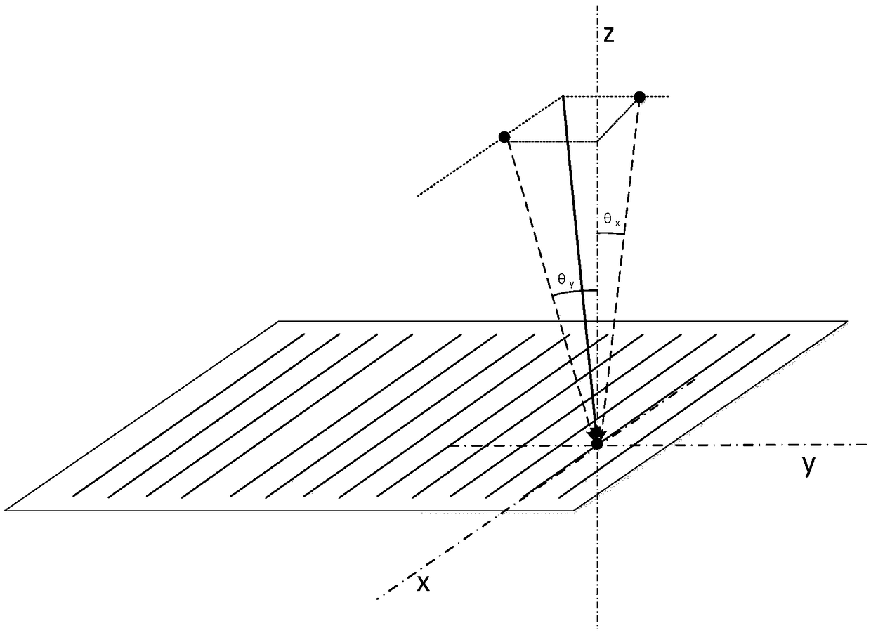
[0051] If the angle of deflection θ of the incident light relative to the vertical x components and theta y The components are all 1μrad, when the total diffraction times is 4, refer to Figure 4 , namely θ x...


PUM


Abstract

The invention discloses a blazed grating based beam deflection angle amplifying unit. The blazed grating based beam deflection angle amplifying unit includes beam deflection angle amplifying subunits;each beam deflection angle amplifying subunit includes two blazed gratings; if an incident angle of a beam incident on the blazed grating is i0, the diffraction angle of the diffracted light containing the main energy of the beam is Theta 0; an included angle between the two blazed gratings is Theta0-i0, so that the incident beam can be diffracted back and forth between the two blazed gratings for multiple times, and the incident angle and the diffraction angle of the incident light are identical in the two blazed gratings. The incident angle i0 and the diffraction angle Theta0 are adjusted,so that the deflection amount of the diffracted light is larger than the deflection amount of the incident light when the incident light is deflected, and multiple diffraction amplifications of the deflection amount of the incident light can be realized. The method can achieve multiple diffraction amplifications of the deflection amount of the incident light.

Description

technical field [0001] The present invention relates to the technical field of beam transmission angle measurement, and more particularly, to a beam deflection angle amplification unit based on a blazed grating. Background technique [0002] Angle measurement is an important part of geometric measurement technology, and optical angle measurement has many advantages such as high precision, non-contact, wide range of application, and many types, so it has become an indispensable detection method in precision testing. At present, the commonly used optical angle measurement methods mainly include optical dividing head method, polygonal prism method, photoelectric encoding method, self-collimation method, parallel interferogram method, circular grating method, optical internal reflection method, laser interferometry and ring laser method. law etc. [0003] Based on the existing angle measurement scheme, if the deflection amount of the incident light can be amplified, and the amp...

Claims


Application Information

Patent Timeline
IPC IPC(8): G01B11/26
CPCG01B11/26
Inventor 刘陈王锦耀刘德明徐镜荃秦思怡朱广颂邵叶定蔡先勇
Owner HUAZHONG UNIV OF SCI & TECH
Why Eureka
Try Eureka