
Capsule robot in three-dimensional closed unstructured space and relative positioning method of object to be tested

A capsule robot, relative positioning technology, applied in instruments, measuring devices, surveying and navigation, etc., can solve problems that have not yet been raised

Inactive Publication Date: 2018-11-06
DALIAN UNIV OF TECH
View PDF6 Cites 7 Cited by
  • Summary
  • Abstract
  • Description
  • Claims
  • Application Information

AI Technical Summary

Problems solved by technology

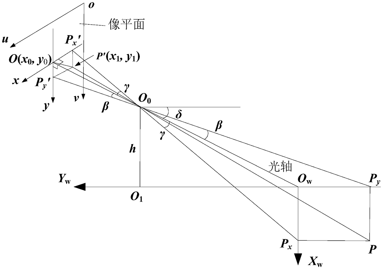
[0006] At present, no one has proposed a relative positioning method for the capsule robot and the target to be measured based on the fusion of magnetic field and vision. The outstanding feature of this positioning method is that it does not need to construct artificial landmarks and maps required in the traditional positioning of mobile robots, and does not need to add additional Other detection and measurement devices can obtain various key information for the positioning of the capsule and the target to be measured only by relying on the camera vision of the capsule robot combined with its own fixed-point hovering and attitude adjustment function

Method used


Image

  • Capsule robot in three-dimensional closed unstructured space and relative positioning method of object to be tested
  • Capsule robot in three-dimensional closed unstructured space and relative positioning method of object to be tested
  • Capsule robot in three-dimensional closed unstructured space and relative positioning method of object to be tested

Examples


Embodiment 1

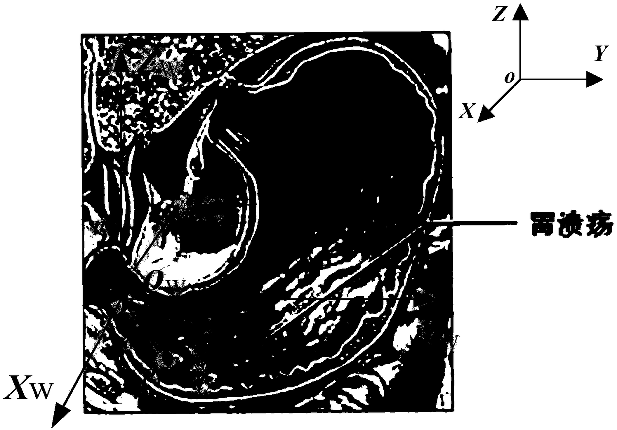
[0073] When the capsule robot is in the lower part of the stomach, the positioning of the capsule robot and the target to be measured in the stomach can be implemented according to the following steps:

[0074] (1) After the capsule robot enters the area to be tested (such as Figure 3a shown), through the side swing joystick e 1 with pitch stick e 2 Make the side swing angle θ and the pitch angle δ of the magnetic vector axis change within 0-360° and 0-90° respectively, and the rotating magnetic vector interacts with the radially magnetized NdFeB ring driver embedded in the capsule robot. Under the dynamic effect, the axis of the capsule robot always follows the axis of the rotating magnetic vector to change its orientation and keep consistent with it, thus driving the capsule camera to realize the panoramic observation function based on fixed-point hovering and attitude adjustment in the area to be measured. The camera transmits the real-time images captured by wireless to...

Embodiment 2

[0079] When the capsule robot is in the upper region of the stomach, reference embodiment 1 can carry out the positioning operation according to the following steps:

[0080] (1) After the capsule robot moves to the upper stomach area (such as Figure 5a shown), through the side swing joystick e 1 with pitch stick e 2 Make the side swing angle θ and the pitch angle δ of the magnetic vector axis change within 0-360° and 0-90° respectively, and the rotating magnetic vector interacts with the radially magnetized NdFeB ring driver embedded in the capsule robot. Under the dynamic effect, the axis of the capsule robot always follows the axis of the rotating magnetic vector to change its orientation and keep consistent with it, thus driving the capsule camera to realize the panoramic observation function based on fixed-point hovering and attitude adjustment in the stomach. The camera will transmit the real-time image to the human-computer interaction interface through wireless. Wh...


PUM


Abstract

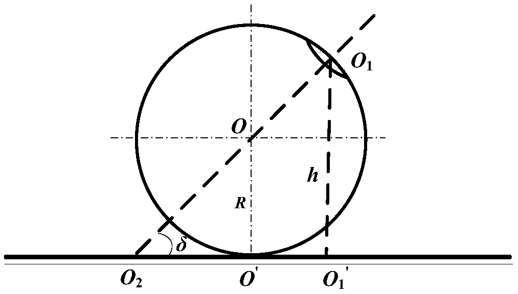
The invention belongs to the technical field of automation engineering and relates to a capsule robot in a three-dimensional closed unstructured space and a relative positioning method of an object tobe tested. The method comprises wirelessly transmitting real-time images obtained when a capsule robot is hovering at spot and is subjected to attitude adjustment to a human-computer interaction interface, carrying out image processing on the acquired images to identify and extract target feature points, and transforming a distance between the object area to a camera into a distance between the optic center of the camera to a specific feature point according to a monocular vision ranging principle. The method is a positioning method for determining the positions of the capsule robot and the object to be tested relative to the reference position in the area to be detected through changing a magnetic vector axis direction to drive a capsule camera to carry out feature target search in the area to be detected in situ, determining a spatial distance of the capsule robot and the object to be tested relative to the reference position according to the camera images, combining pitch angle andside swing angle information of the capsule robot when acquiring the target features in two processes and using the spatial geometric relationship of the capsule robot and the object to be tested relative to the reference positions.

Description

technical field [0001] The invention belongs to the technical field of automation engineering and relates to a relative positioning method for a capsule robot and a target to be measured in a three-dimensional closed unstructured space. Background technique [0002] The localization of mobile robots, especially in unknown, complex and dynamic unstructured environments (such as the human gastrointestinal tract) is a key problem to be solved in the current research field of mobile robots. [0003] The existing localization technologies for autonomous mobile robots can be divided into the following categories: 1. Landmark-based localization technology. Landmarks refer to special objects with obvious characteristics that can be recognized by mobile robot sensors. Landmarks have fixed and known positions in the global environment. The main task of mobile robot positioning is to reliably identify landmarks and calculate the position of mobile robots. The level of its positioning ...

Claims


Application Information

Patent Timeline
IPC IPC(8): G01C21/00G01C21/08G01C11/00
CPCG01C11/00G01C21/005G01C21/08
Inventor 张永顺杨慧远田丰王殿龙
Owner DALIAN UNIV OF TECH
Learn More