
Test device and test method for exploring surface drag reduction mechanism

A test device and mechanism technology, applied in the field of drag reduction test, can solve problems such as difficult processing, large resistance value error, bulky volume, etc., and achieve the effects of reducing research and development costs, convenient replacement, and simple structure

Pending Publication Date: 2018-11-06
HUAZHONG UNIV OF SCI & TECH
View PDF6 Cites 2 Cited by
  • Summary
  • Abstract
  • Description
  • Claims
  • Application Information

AI Technical Summary

Problems solved by technology

[0005] 1) Most of the current drag reduction test research is carried out in large water tunnels and tanks, and mainly focuses on evaluating the drag reduction effect. Due to the large size of the overall equipment, huge equipment maintenance and test surface preparation costs will be incurred
[0006] 2) If the drag reduction effect is measured at the laboratory level, the direct detection of the resistance has a large numerical error due to the small plane
[0007] 3) In terms of research on the mechanism of drag reduction, the current experimental research methods focus more on the macroscopic velocity field, while less observations are made on the microscopic velocity field caused by drag reduction. Compared with numerical simulation, a large number of details are ignored
[0008] 4) Most of the current pipeline drag reduction test research does not have a replaceable structure, which is difficult to process and makes the test inconvenient

Method used


Image

  • Test device and test method for exploring surface drag reduction mechanism
  • Test device and test method for exploring surface drag reduction mechanism
  • Test device and test method for exploring surface drag reduction mechanism

Examples


Embodiment Construction

[0042] In order to make the object, technical solution and advantages of the present invention clearer, the present invention will be further described in detail below in conjunction with the accompanying drawings and embodiments. It should be understood that the specific embodiments described here are only used to explain the present invention, not to limit the present invention. In addition, the technical features involved in the various embodiments of the present invention described below may be combined with each other as long as they do not constitute a conflict with each other.

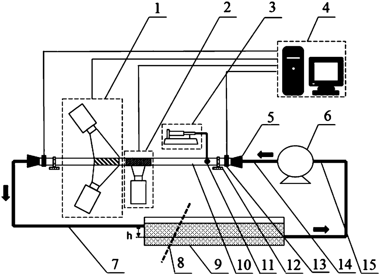
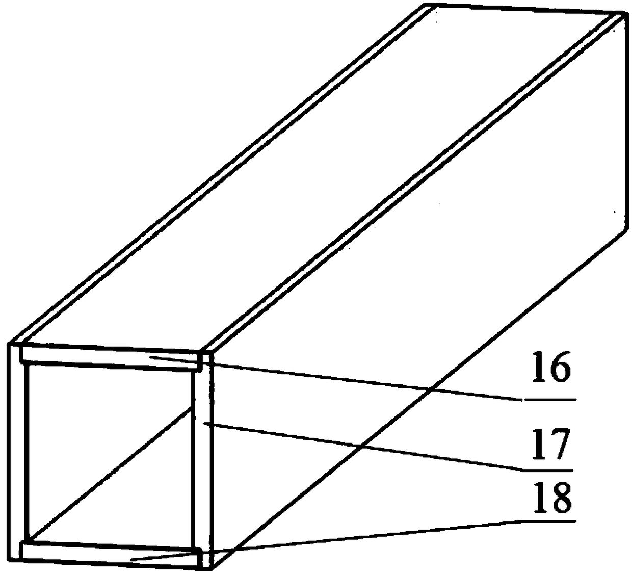
[0043] refer to figure 1 , figure 2 , a test device for exploring the mechanism of surface drag reduction, including a water storage tank 9, a peristaltic pump 6, an air injection pump 3, a pressure sensor 13, a PIV measuring instrument 1, a Micro-PIV measuring instrument 2 and a computer receiving and processing system 4, wherein,

[0044] The water storage tank 9 has a fluid inlet and a flu...


PUM


Abstract

The invention belongs to the drag reduction test technology field and discloses a test device for exploring the surface drag reduction mechanism. The test device comprises a water storage tank, a peristaltic pump, an air injection pump, pressure sensors, a PIV measuring instrument, a Micro-PIV measuring instrument and a computer receiving and processing system, wherein the water storage tank has afluid inlet and a fluid outlet, the fluid outlet is connected with an inlet of the peristaltic pump through a first conveying pipeline, an outlet of the peristaltic pump is connected with a second conveying pipeline, the fluid inlet of the water storage tank is connected with a third conveying pipeline, the pressure sensors are two, each pressure sensor is separately mounted to one end of a to-be-tested pipeline, and the PIV measuring instrument and the Micro-PIV measuring instrument are used to measure the velocity field of the fluid in the to-be-tested pipeline. The test device is advantaged in that a relatively small sample can be used to test the drag reduction effect of a drag reduction surface, the test device is beneficial to reduce research and development cost of the drag reduction technology, moreover, the test device has a simple structure, and the to-be-tested pipeline is convenient to replace.

Description

technical field [0001] The invention belongs to the technical field of drag reduction testing, and more specifically relates to a test device and a test method for exploring the mechanism of surface drag reduction. Background technique [0002] Due to its own viscosity, there will be resistance between the fluid and the surrounding interface during the flow process, such as ship resistance, underwater vehicle resistance and transportation pipeline resistance. [0003] With the intensification of the energy crisis, the research on fluid flow drag reduction technology applied in different scenarios has become a hot spot at home and abroad. The research methods mainly include theoretical analysis, numerical simulation and experiment. Among them, the test method is considered to be the most important means to study surface drag reduction technology because of its accuracy and authenticity. [0004] However, the existing test methods have certain defects, mainly as follows: [...

Claims


Application Information

Patent Timeline
Patent Type & Authority Applications(China)
IPC IPC(8): G01M10/00
CPCG01M10/00Y02T70/10
Inventor 姜羽泽叶晓明朱世新徐继旺聂富成
Owner HUAZHONG UNIV OF SCI & TECH
Learn More