Detecting device for fiber line losses and fiber end surface losses

An optical fiber line and optical fiber end face technology, which is applied in the field of optical fiber line loss and fiber optic connector end quality inspection, can solve the problems of confusion in the identification of construction responsibilities, inability to use large quantities of equipment, and difficult equipment to use, so as to facilitate engineering construction and supervision, It is conducive to large-scale promotion and the effect of reducing equipment investment costs

Pending Publication Date: 2018-11-06
NANJING XIUDEA COMM TECH CO LTD
View PDF0 Cites 2 Cited by
  • Summary
  • Abstract
  • Description
  • Claims
  • Application Information

AI Technical Summary

Problems solved by technology

[0002] At present, in the FTTH fiber-to-the-home project, the non-preset optical fiber connector has no connection point in the V-shaped fastening groove because the prepared on-site optical fiber directly passes through the surface of the ferrule, which greatly reduces the optical performance such as insertion loss after termination However, the optical power meter carried by the construction personnel can only measure the loss of the optical fiber line, and cannot detect the loss of the fiber end face of the fiber optic connector that is terminated on site. The loss of the end face leads to confusion in the judgment of construction responsibilities, which seriously affects the experience of operators on non-pre-installed optical fiber products
[0003] The product currently available on the market that can simultaneously detect fiber line loss and fiber end face loss is an optical time domain reflectometer, which uses the reflection loss phenomenon generated by light waves at the fiber loss point and th

Method used


Image

  • Detecting device for fiber line losses and fiber end surface losses
  • Detecting device for fiber line losses and fiber end surface losses
  • Detecting device for fiber line losses and fiber end surface losses

Examples


Embodiment Construction

[0023] In order to make the above objects, features and advantages of the present invention more obvious and comprehensible, specific implementations of the present invention will be described in detail below in conjunction with the accompanying drawings.

[0024] In the following description, a lot of specific details are set forth in order to fully understand the present invention, but the present invention can also be implemented in other ways different from those described here, and those skilled in the art can do it without departing from the meaning of the present invention. By analogy, the present invention is therefore not limited to the specific examples disclosed below.

[0025] Second, "one embodiment" or "an embodiment" referred to herein refers to a specific feature, structure or characteristic that may be included in at least one implementation of the present invention. "In one embodiment" appearing in different places in this specification does not all refer to ...


PUM


Abstract

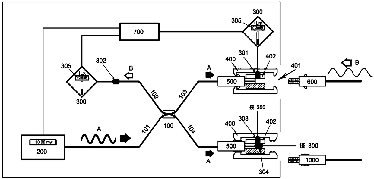
The invention discloses a detecting device for fiber line losses and fiber end surface losses. The detecting device comprises a light splitter, a stable light source, an optical power meter, an adapter, a standard connector, a fiber connector, a calibration connector. The light splitter is connected with the stable light source through a first female port of the light splitter, is connected with the optical power meter through a second female port of the light splitter, and is connected with the standard connector through a first branch port of the light splitter. The optical power meter is respectively connected with a lateral detector and a forward detector; the lateral detector is installed in the adapter to detect the fiber end surface losses; the forward detector is connected to a second female port of the light splitter to detect the fiber line losses. The construction worker is able to test the fiber line losses and the connection quality of the field formed fiber connector respectively by carrying one device; the engineering construction and monitoring are carried out conveniently; and the construction field device investment cost is lowered. The detecting device having a small size and high reliability is suitable for large-area popularization.

Description

technical field [0001] The invention relates to the field of optical fiber line loss and optical fiber connector termination quality detection. The device connects a stable light source, a forward detector of an optical power meter, and a standard connector of a detection end through an optical splitter. The optical fiber connector is connected to the standard connector through an adapter. The connectors are coupled together and the side detector of the optical power meter is installed in the adapter. After the detection light wave emitted by the stable light source is branched by the optical splitter, when part of the detection light wave reaches the coupling point, the intensity of the refraction and diffuse reflection light received by the side detector can be used to judge the loss of the fiber end face; the communication light wave enters through the coupling point of the fiber optic connector In the optical splitter, part of the communication light waves finally reaches ...

Claims


Application Information

Patent Timeline
IPC IPC(8): G01M11/00
CPCG01M11/00
Inventor 吕根良
Owner NANJING XIUDEA COMM TECH CO LTD
Why Eureka
Try Eureka