
Prefabricated optical cable connector and welding-free optical fiber distribution case

A technology of optical fiber distribution box and prefabricated optical cable, which is applied in the coupling of optical waveguide and fiber mechanical structure, etc. It can solve the problems of difficulty in guaranteeing the quality of fusion splicing at the construction site, high repair rate of repeated fusion splicing, and heavy workload of on-site fusion splicing, etc., and achieves convenience The effects of post-operation management and maintenance, improvement of project construction quality, and shortened on-site construction time

Pending Publication Date: 2018-11-06
STATE GRID CORP OF CHINA +6
View PDF0 Cites 0 Cited by
  • Summary
  • Abstract
  • Description
  • Claims
  • Application Information

AI Technical Summary

Problems solved by technology

[0003] The disadvantages of the prior art of optical fiber fusion splicing above are that it is difficult to guarantee the quality of fusion splicing at the construction site, resulting in large optical transmission loss and poor consistency after splicing multi-core optical fibers, high repair rate of repeated splicing, heavy workload of on-site splicing, long construction period, and high splicing costs. higher
At the same time, because there is no uniform standard for the height and wiring method of the optical fiber fusion splicing distribution box, resulting in many specifications of the fusion splicing distribution box, irregular wiring, and unsightly wiring, which brings inconvenience to later operation and maintenance.

Method used


Image

  • Prefabricated optical cable connector and welding-free optical fiber distribution case
  • Prefabricated optical cable connector and welding-free optical fiber distribution case
  • Prefabricated optical cable connector and welding-free optical fiber distribution case

Examples


Embodiment Construction

[0028] The present invention will be described in detail below in conjunction with the accompanying drawings. However, it should be understood that the accompanying drawings are provided only for better understanding of the present invention, and they should not be construed as limiting the present invention.

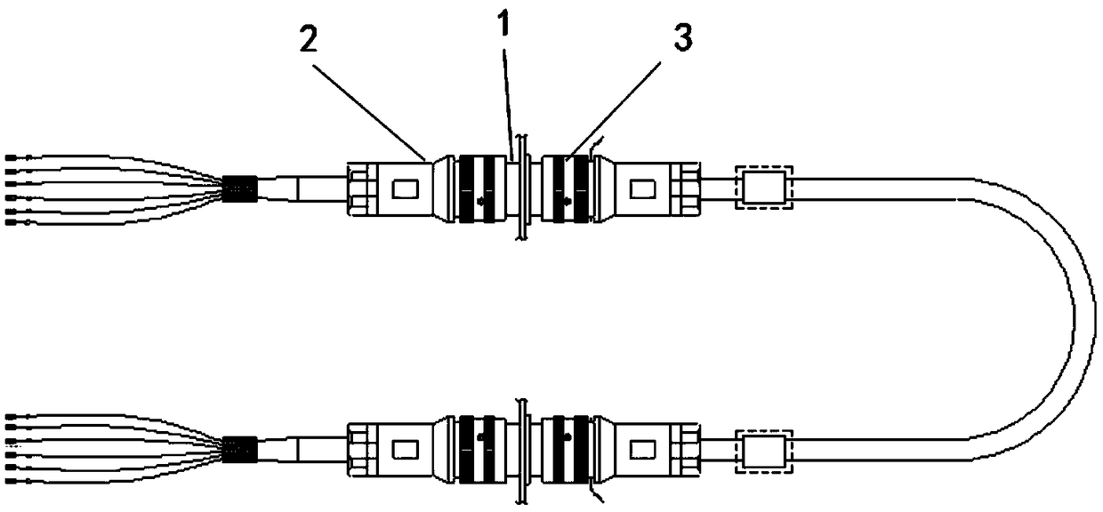
[0029] Such as figure 1 As shown, the prefabricated optical cable connector provided by the present invention includes a prefabricated optical cable adapter 1 , a prefabricated optical cable plug 2 and a prefabricated optical cable socket 3 .

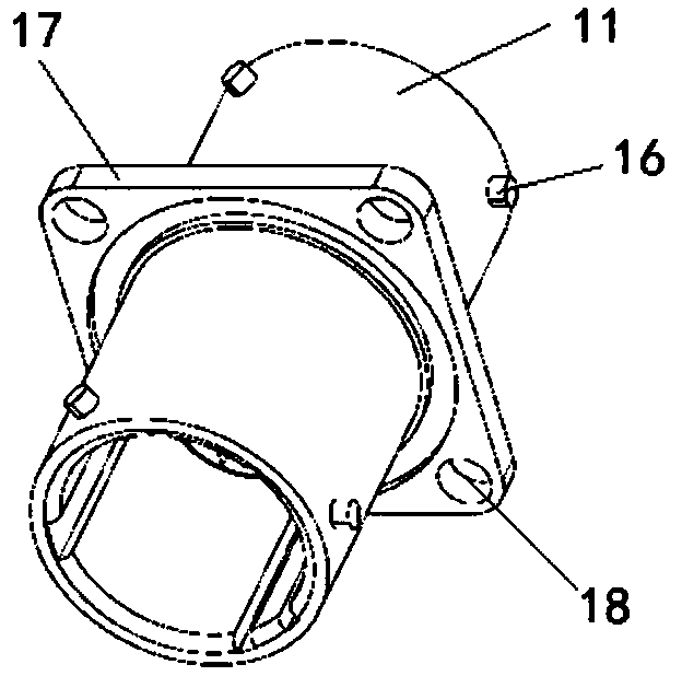
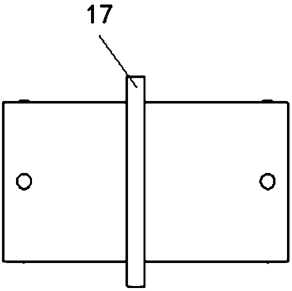
[0030] Such as Figure 2-4 As shown, the prefabricated optical cable adapter 1 includes a cylindrical base 11 with openings at both ends. A radial main keyway 12 and a number of radial auxiliary keyways 13 are provided at intervals on the inner side of the cylindrical base 11. Each of the auxiliary keyways 13 of the present invention The number is four, and this is taken as an example, not limited thereto. A connecting plate 1...


PUM


Abstract

The present invention relates to a prefabricated optical cable connector and a welding-free optical fiber distribution case. The prefabricated optical cable connector comprises a prefabricated opticalcable adapter, a prefabricated optical cable plug and a prefabricated optical cable socket; the prefabricated optical cable adapter comprises a cylindrical base body with openings at two ends, radialprimary key grooves and a plurality of radial assistant key grooves are arranged at the inner sides of the two ends of the cylindrical base body at intervals in the circumference, a connection plateis fixedly arranged at the center of the inner side of the cylindrical base body, and the connection plate is provided with a radial T-shaped adaptive hole; the prefabricated optical cable plug and the prefabricated optical cable socket are the same in structure, and a P guidance needle is fixedly arranged at the front end of the high-density beam concentration optical fiber connector of the prefabricated optical cable plug; and the front end of the beam concentration optical fiber connector of the prefabricated optical cable socket is a P guidance hole matching with the P guidance needle of the beam concentration optical fiber connector of the prefabricated optical cable plug.

Description

technical field [0001] The invention relates to a prefabricated optical cable connector and a non-melting optical fiber distribution box, and relates to the technical field of optical fiber accessories. Background technique [0002] When ordinary optical cables (optical cables containing more than 2 cores of optical fibers) are laid and connected to optical fiber distribution boxes or optical fiber distribution devices, the sheath layer must be stripped one by one from the optical fibers, and the end faces of the optical fibers must be cut with a special cutter. Then put the two optical fibers that need to be fused into the left and right sides of the fusion channel of the optical fiber fusion machine on the construction site, align the end faces of the optical fibers and heat and weld them together. Multiple optical fibers need to be repeatedly fused. Perform fiber insertion loss or return loss detection one by one. If the fiber loss value is judged to be unqualified, the f...

Claims


Application Information

Patent Timeline
Patent Type & Authority Applications(China)
IPC IPC(8): G02B6/38G02B6/44
CPCG02B6/3821G02B6/3825G02B6/3831G02B6/4446G02B6/4452
Inventor 宋璇坤肖智宏方贞泽韩柳张锐邱新娟李军闫培丽吴聪颖郭亚昌王晓旭薛旭恒赖清平谷松林刘鹏李铁臣冯腾刘文轩申燕飞宋晓帆庄博李妍陈婧华鲁昭南
Owner STATE GRID CORP OF CHINA
Learn More