Optical cable production equipment and system

A technology for production equipment and production systems, applied in the directions of light guides, optics, optical components, etc., can solve the problems of difficult to guarantee the distribution position of the reinforcement, uneven distribution of the strength of the optical cable, unstable quality of the optical cable, etc., to achieve uniform distribution of traction force, tensile strength Ability to highlight, evenly distributed effect

Inactive Publication Date: 2018-11-06
上海富瑞电缆股份有限公司
View PDF7 Cites 4 Cited by
  • Summary
  • Abstract
  • Description
  • Claims
  • Application Information

AI Technical Summary

Problems solved by technology

[0004] Optical cables usually reinforce the optical cable by distributing strength members along the circumferential direction of the optical fiber. During the processing of the optical cable, the protective material needs to be extruded through the extrusion equipment to wrap the optical fiber and the strength member, so that the strength member is fixedly connected to the optical fiber. During the output process, it is difficult to ensure the distribution position of the strength member, which makes the intensity distribution of the optical cable uneven, which may lead to a decrease in local strength and lead to weak points in the use of the optical cable to cause damage, resulting in unstable quality of the optical cable, and there is still room for improvement.

Method used


Image

  • Optical cable production equipment and system
  • Optical cable production equipment and system
  • Optical cable production equipment and system

Examples


Embodiment 1

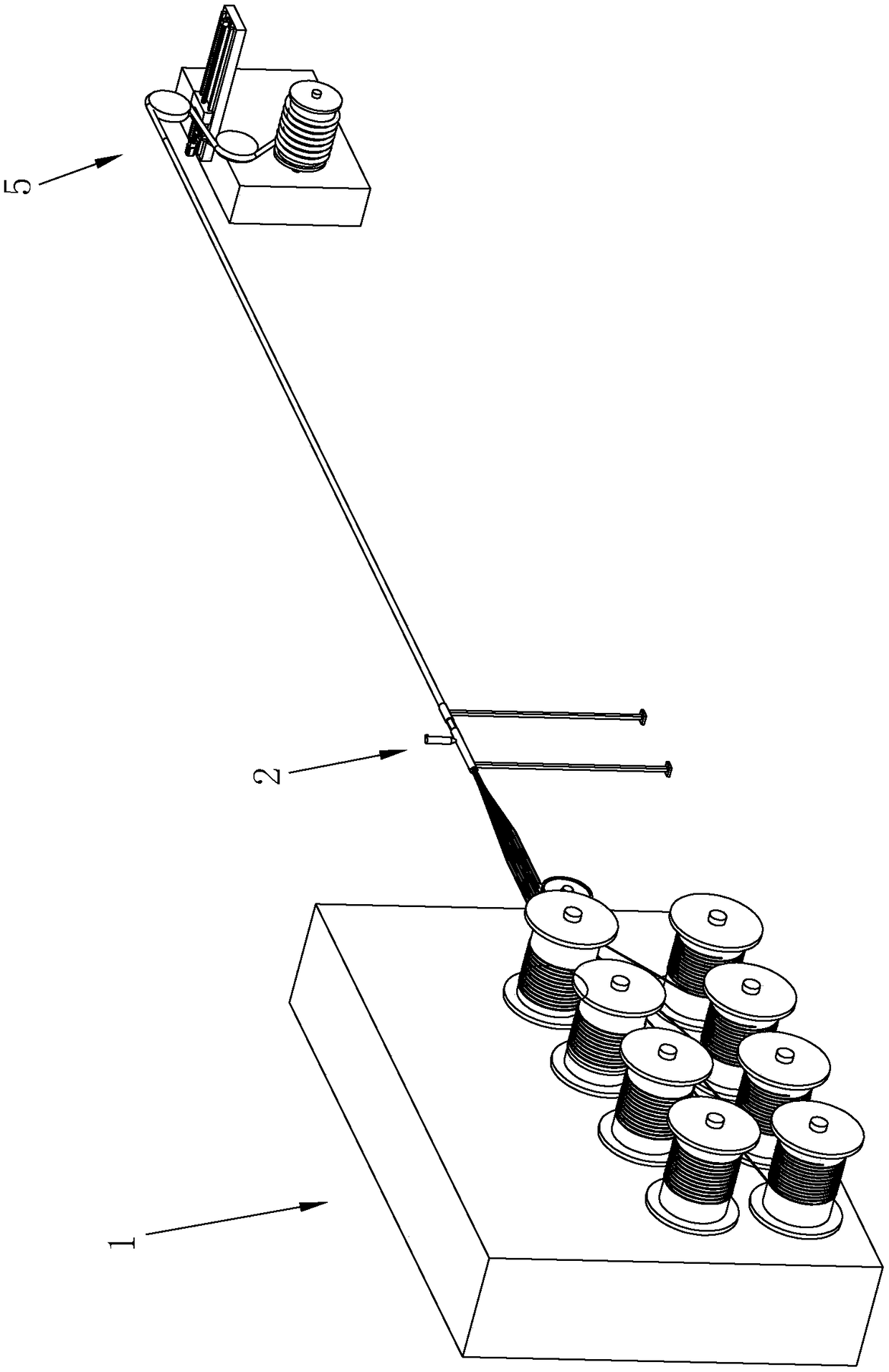
[0047] A kind of optical cable production equipment, refer to figure 1 , including an unwinding device 1, an extruding device 2 and a winding device 5 arranged in sequence, wherein the unwinding device 1 is used to guide the optical fiber and strengthen the strength of the optical cable, and the extruding device 2 is used to extrude the protective material To wrap optical fibers and strength members.

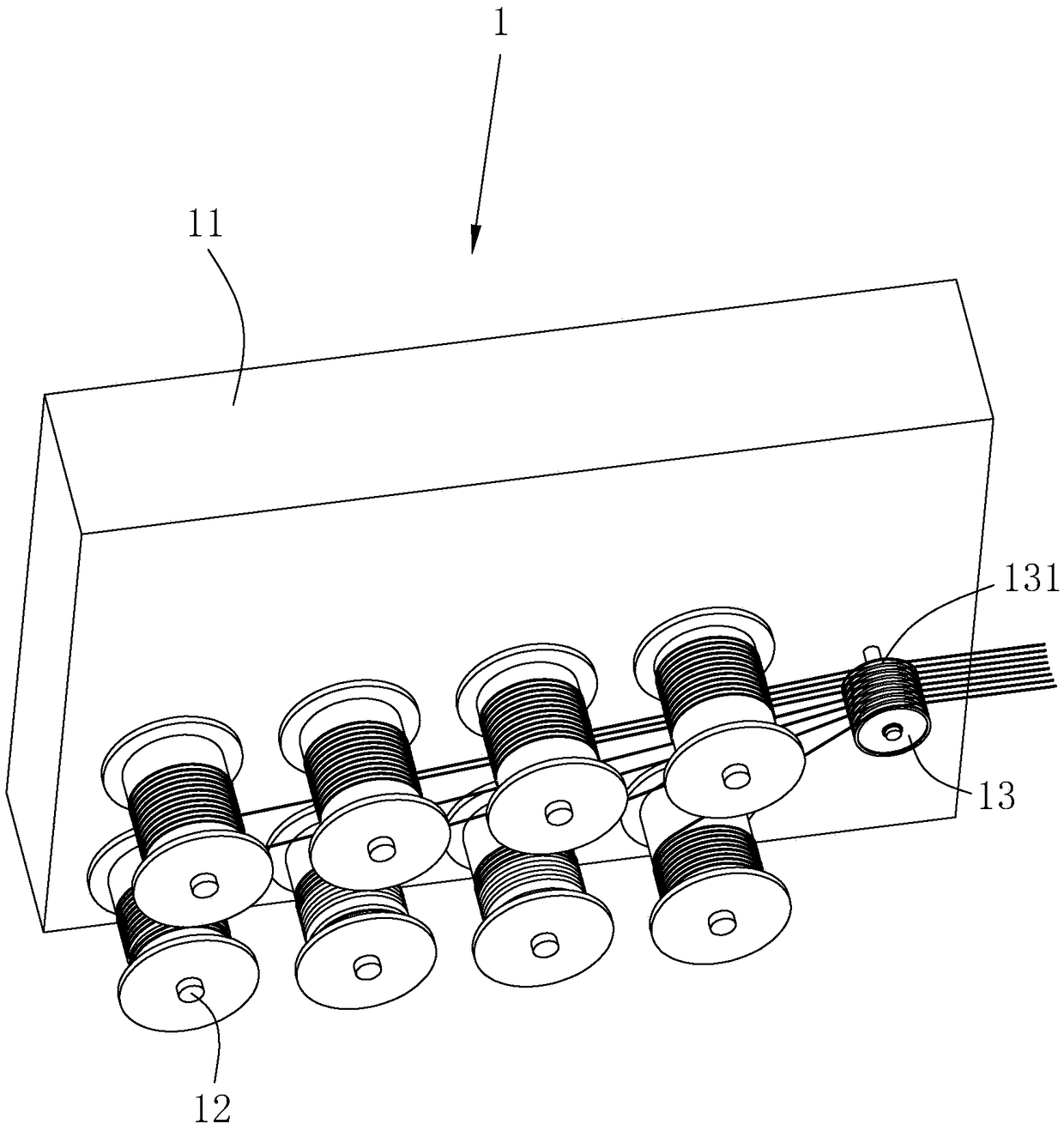
[0048] refer to figure 2 , the guiding device 1 comprises a guiding seat 11, on which the guiding seat 11 is rotatably connected with several rotating shafts 12 parallel to each other. Sleeved on the rotating shaft 12 to follow the rotating shaft 12 to rotate, the guide seat 11 is connected with a damping plate (not shown) abutting on the rotating shaft 12 .

[0049] The guide device 1 also includes a guide wheel 13 that is rotatably connected to the guide seat 11, the axis of rotation of the guide wheel 13 is parallel to the axis of the rotating shaft 12, and the sidewall of...

Embodiment 2

[0067] A kind of optical cable production system, refer to Image 6 , including the unwinding device 1, the extruding device 2, the tensioning device 4 and the rewinding device 5 arranged in sequence, the optical cable enters the rewinding device 5 after passing through the tensioning device 4, wherein the unwinding device 1, the extruding device 2 and the rewinding device 5 The winding device 5 is the unwinding device 1 , the extruding device 2 and the winding device 5 in the first embodiment.

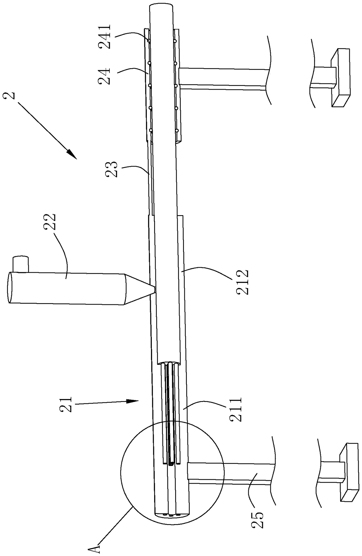
[0068] refer to Figure 8 , the tensioning device 4 includes a tensioning support 41, and the tensioning support 41 is rotatably connected with a front roller 421 and a rear roller 431. There are two pairs of front rollers 421, and each pair of front rollers 421 is opposite to each other along the radial direction of the optical cable. The front rollers 421 are evenly distributed around the circumference of the optical cable to form a front roller group 42, and there are two pairs of...


PUM


Abstract

The invention relates to the technical field of photoelectric machineries and in view of the problem of optical cable production quality instability, provides optical cable production equipment and system. The optical cable production equipment, in the technical scheme, comprises an unwinding device, an extruding device and a winding device arranged in sequence, wherein the extruding device comprises an extruding die and a protection material extruding part; the extruding die comprises a positioning pipe; the positioning pipe is provided with an optical fiber hole and a plurality of strength member holes distributed along the circumference of the optical fiber hole; the extruding die also comprises an injecting pipe; the axis of the injecting pipe is consistent with that of the positioningpipe; the optical fiber and the strength members pass through the injecting pipe and gaps are left with the inner wall of the injecting pipe; and the extruding head of the protection material extruding part is communicated with the injecting pipe. Through enabling the optical fiber to pass through the optical fiber hole and enabling the strength members to pass through the strength member holes so as to position the optical fiber and the strength members, the optical cable is wound through the winding device, the optical fiber and the strength members are in a tensioning state, and thus, accurate positioning is achieved when the optical fiber and the strength members pass through the injecting pipe.

Description

technical field [0001] The present invention relates to the technical field of optoelectronic machinery, more specifically, it relates to a kind of optical cable production equipment and system. Background technique [0002] Optical cables are manufactured to meet optical, mechanical or environmental performance specifications. It is a communication cable assembly that uses one or more optical fibers placed in a sheath as a transmission medium and can be used individually or in groups. Optical cables are mainly composed of optical fibers (glass filaments as thin as hair), plastic protective sleeves and plastic sheaths. There are no metals such as gold, silver, copper, and aluminum in optical cables, and generally have no recycling value. An optical cable is a communication line in which a certain number of optical fibers form a cable core in a certain way, and is covered with a sheath, and some are also covered with an outer sheath to realize optical signal transmission. ...

Claims


Application Information

Patent Timeline
IPC IPC(8): G02B6/44
CPCG02B6/4432G02B6/4479
Inventor 肖建军
Owner 上海富瑞电缆股份有限公司
Why Eureka
Try Eureka