Detection debugging method of autonomous vehicle throttle control system

A technology of automatic driving and throttle control, applied in general control systems, control/regulation systems, test/monitoring control systems, etc. Other circuit damage and other problems, to achieve the effect of improving production economic benefits, shortening production cycle, and saving production costs

Inactive Publication Date: 2018-11-06
深圳市智尊保汽车科技有限公司
View PDF30 Cites 8 Cited by
  • Summary
  • Abstract
  • Description
  • Claims
  • Application Information

AI Technical Summary

Problems solved by technology

This accelerator modification method for self-driving cars mainly has the following defects: 1. The throttle control system that has not been tested is directly installed after the electronic control system of the vehicle. Due to the quality of components, welding process, assembly process, etc. There will be certain faults. If there is a short-circuit fault in the electronic control system after production, it will cause damage to the power supply and other circuits of the original electronic control system of the car after it is directly installed in the electric control system of the car, which will cause damage to the later system. It is very difficult to debug. In addition, when replacing the man-made damaged electronic control system of the original car to troubleshoot, it will also increase additional costs and affect the factory consistency of the original car electronic control system. There are certain potential safety hazards.
2. Due to the small operating space of the vehicle, it is not convenient to adjust the relevant circuit parameters of the throttle control system on the vehicle, and after the connection of the additional throttle control system is completed, the entire system needs to be powered on for parameter adjustment, which will affect the original vehicle. The control system works normally. Therefore, this method is not convenient for later modification and debugging, which will affect the progress of the project and prolong the production cycle accordingly.
[0003] Moreover, the usual detection and debugging only detects one DUT, and the detection efficiency is low
[0004] At present, there is no special detection and debugging method to detect and calibrate the performance and parameters of the throttle control system after production. Therefore, it is very useful to design a detection and debugging method specially applied to the throttle control system of autonomous vehicles. necessary

Method used


Image

  • Detection debugging method of autonomous vehicle throttle control system
  • Detection debugging method of autonomous vehicle throttle control system
  • Detection debugging method of autonomous vehicle throttle control system

Examples


Embodiment 1

[0045] This embodiment provides a method for detecting and debugging an accelerator control system of an automatic driving vehicle. A detection and debugging system is used to detect and debug an accelerator control system of an automatic driving vehicle.

[0046] The detection and debugging system is especially suitable for the throttle control system of an automatic driving vehicle.

[0047] 1. Throttle control system for autonomous vehicles

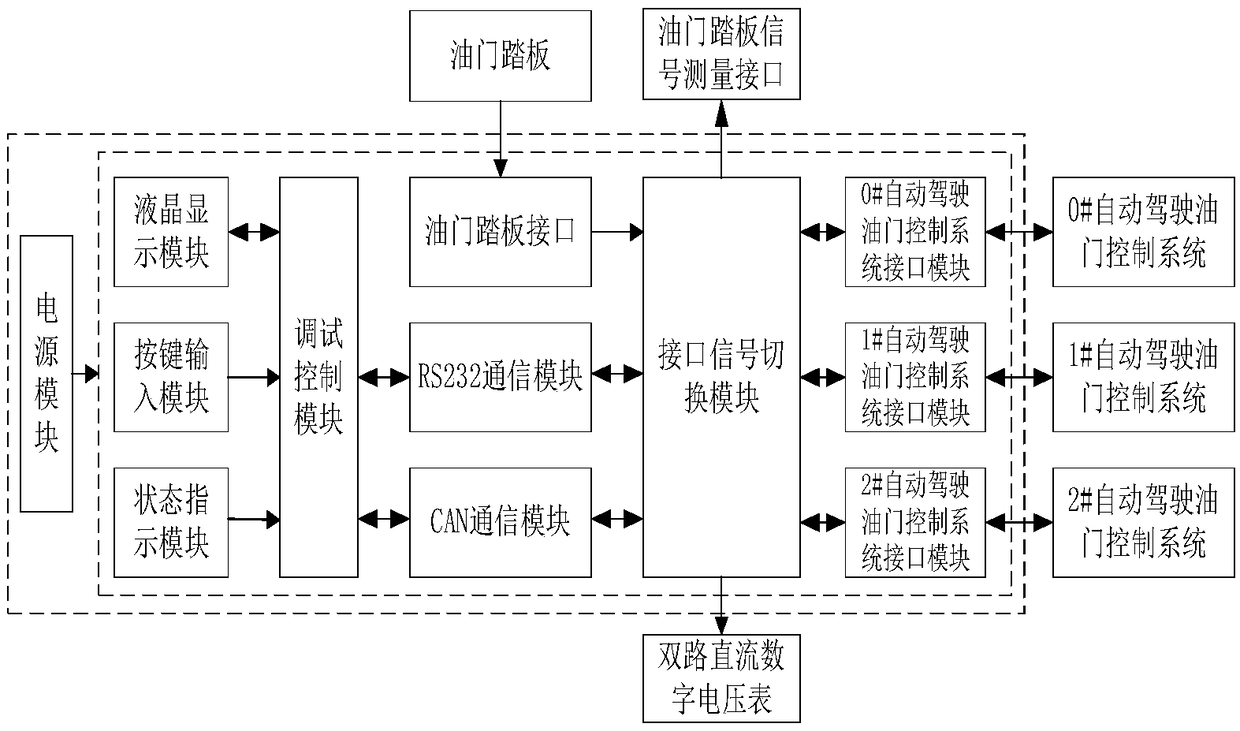
[0048] Such as Figure 17 As shown, the accelerator control system of an automatic driving vehicle includes an accelerator pedal signal switching module, a reference voltage module, an accelerator pedal analog signal generation module, a microcontroller module, a CAN network interface module, a host computer communication interface module, and a power module; the accelerator pedal signal switching The modules are externally connected to the accelerator pedal and the motor electronic control module; the engine electronic control module...

Embodiment 2

[0105] The detection and debugging method of this embodiment adopts a multi-channel rapid detection and debugging platform for the throttle control system of an automatic driving vehicle, which includes the multi-channel rapid detection and debugging system for the throttle control system of an automatic driving vehicle in Embodiment 1.

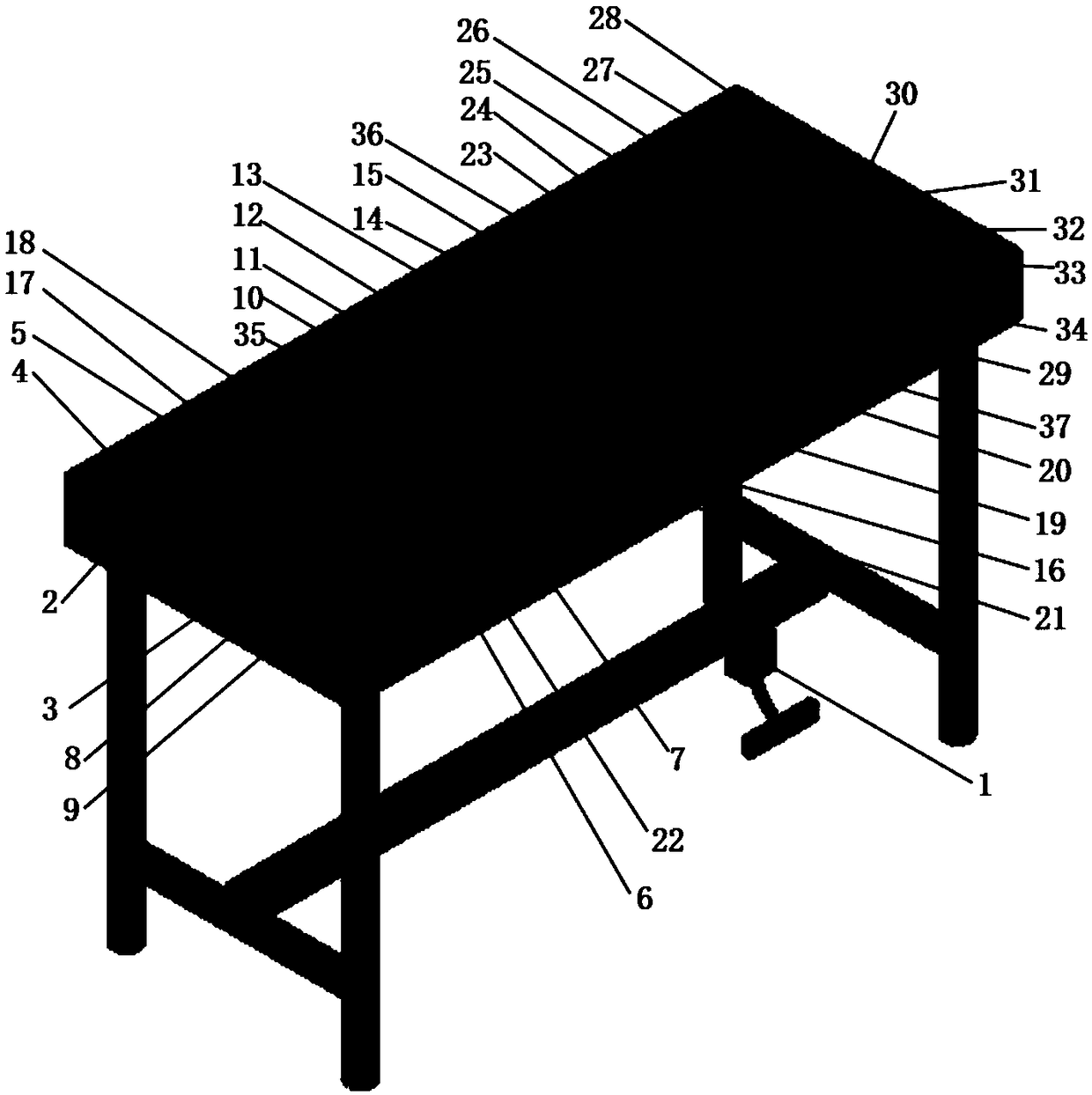
[0106] see figure 1 , the side of the platform is provided with an AC power socket 2 and a main power switch 3; the bottom of the platform is provided with an accelerator pedal device 1, and the accelerator pedal device 1 includes an accelerator pedal and an accelerator pedal position sensor, and the accelerator pedal position sensor is connected to Figure 9 The accelerator pedal sensor interface PS6 in the middle accelerator pedal interface module; the table top of the platform is provided with a power indicator light 4, a manual mode indicator light 17, an automatic mode indicator light 18, a channel 0 indicator light 35, a channel 1 indica...


PUM


Abstract

The invention discloses a detection debugging method of an autonomous vehicle throttle control system. The method includes steps: A, selecting a to-be-detected autonomous vehicle throttle control system; B, setting a driving mode through a button input module of a detection debugging system, wherein the driving mode comprises a manual driving mode and an automatic driving mode; C, entering the manual driving mode for a function test, and determining whether functions of a throttle pedal switching module and a microcontroller module in the manual driving mode are normal; and D, entering the automatic driving mode for the function test, wherein D1, the detection debugging system simulates the vehicle functions and determines whether a CAN network interface and a host computer communication interface which are to be detected are normal, and D2, the detection debugging system simulates the functions of a host computer and determines whether the functions of the microcontroller module and the throttle pedal signal switching module in the automatic driving mode, a throttle pedal simulation signal generation module and a reference voltage module are normal. According to the detection method, the test is simple, and the test efficiency is high.

Description

technical field [0001] The invention relates to the field of automatic driving of automobiles, and more particularly, to a detection and debugging method for an accelerator control system of an automatic driving automobile. Background technique [0002] The accelerator control system for autonomous vehicles is to realize the automatic control of the accelerator for the autonomous vehicle. In the process of automatic driving, no manual participation is required, and the control system realizes the automatic control of the accelerator. In the existing application of this kind of accelerator control system for self-driving car transformation programs, the completed accelerator control system has not been tested and debugged in the early stage, and it is directly installed on the self-driving car. This accelerator modification method for self-driving cars mainly has the following defects: 1. The throttle control system that has not been tested is directly installed after the ele...

Claims


Application Information

Patent Timeline
Patent Type & Authority Applications(China)
IPC IPC(8): G05B23/02
CPCG05B23/0213
Inventor 舒望
Owner 深圳市智尊保汽车科技有限公司
Why Eureka
Try Eureka