Wind cooling heat radiation structure of power battery pack

A power battery pack and heat dissipation structure technology, which is applied to secondary batteries, circuits, electrical components, etc., can solve problems such as uneven fluid distribution, achieve good temperature uniformity and heat dissipation effects, reduce maintenance costs, and reduce temperature differences.

Pending Publication Date: 2018-11-06
辽宁比科新能源股份有限公司 +1
View PDF10 Cites 10 Cited by
  • Summary
  • Abstract
  • Description
  • Claims
  • Application Information

AI Technical Summary

Problems solved by technology

[0007] The object of the present invention is to propose an air-cooled heat dissipation structure of a power battery pack, which has a simple air-cooled heat dissipation structure, in view of the problem that the fluid distribution is uneven and the cooling effect needs to be improved in the existing parallel air-cooled heat dissipation method Reasonable, can improve the heat dissipation problem of the battery under the parallel ventilation mode in a relatively stable state, so that the air fluid distribution inside the box with the power battery pack is uniform, strengthen the heat dissipation of the power battery, reduce the temperature difference of the battery pack, and the temperature distribution is uniform to meet different types of battery pack structures

Method used


Image

  • Wind cooling heat radiation structure of power battery pack
  • Wind cooling heat radiation structure of power battery pack
  • Wind cooling heat radiation structure of power battery pack

Examples


Embodiment 1

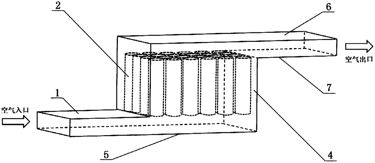
[0048] This embodiment discloses an air-cooled heat dissipation structure for a power battery pack, such as Figure 6 As shown, it includes a box body 4 for accommodating a power battery pack 2 and an air inlet channel 1 and an air outlet channel 7 communicating with the box body 4 , and the overall outer contour is in a Z-shaped structure. The multiple single power batteries of the power battery pack are vertically placed in the box. The air inlet channel 1 and the air outlet channel 7 are respectively arranged on two opposite sides of the box body 4; the bottom surface of the box body is a deflector 5, and the top surface of the box body is a collector plate 6; The deflector 5 is on the same plane as the bottom plate of the air inlet channel 1, and the top plate of the collector plate 6 and the air outlet channel 7 is on the same plane;

[0049] The side of the collector plate 6 close to the box is provided with a shunt 3, that is, the air-cooled heat dissipation structure ...

Embodiment 2

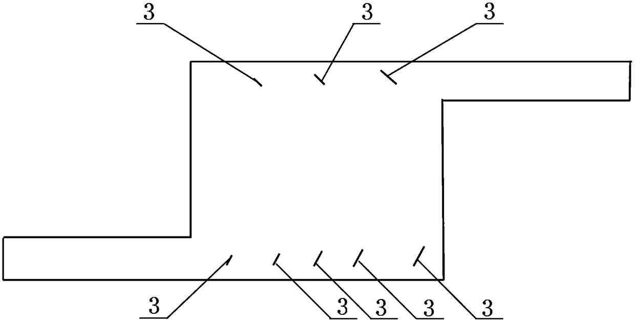
[0053] This embodiment discloses an air-cooled heat dissipation structure for a power battery pack, such as Figure 7 As shown, the air-cooled heat dissipation structure of this embodiment is basically the same as that of Embodiment 1, the difference is that the side of the deflector 5 close to the box is provided with a shunt 3, that is, only the lower side of the battery box is provided with a shunt , the splitters are five pieces, the angle of inclination of the five splitters is 60°, the lengths are 4mm, 6mm, 8mm, 10mm, 12mm, and they are evenly distributed on the lower side of the box at equal intervals.

[0054] When the air fluid enters the air inlet channel 1, it first passes through the interference of the first splitter 3 on the lower side, and then part of the fluid is distributed among the cells close to the air inlet channel 1, and the rest of the air fluid passes through the upper and lower sides of the splitter. The side continues to flow backward, and when it e...

Embodiment 3

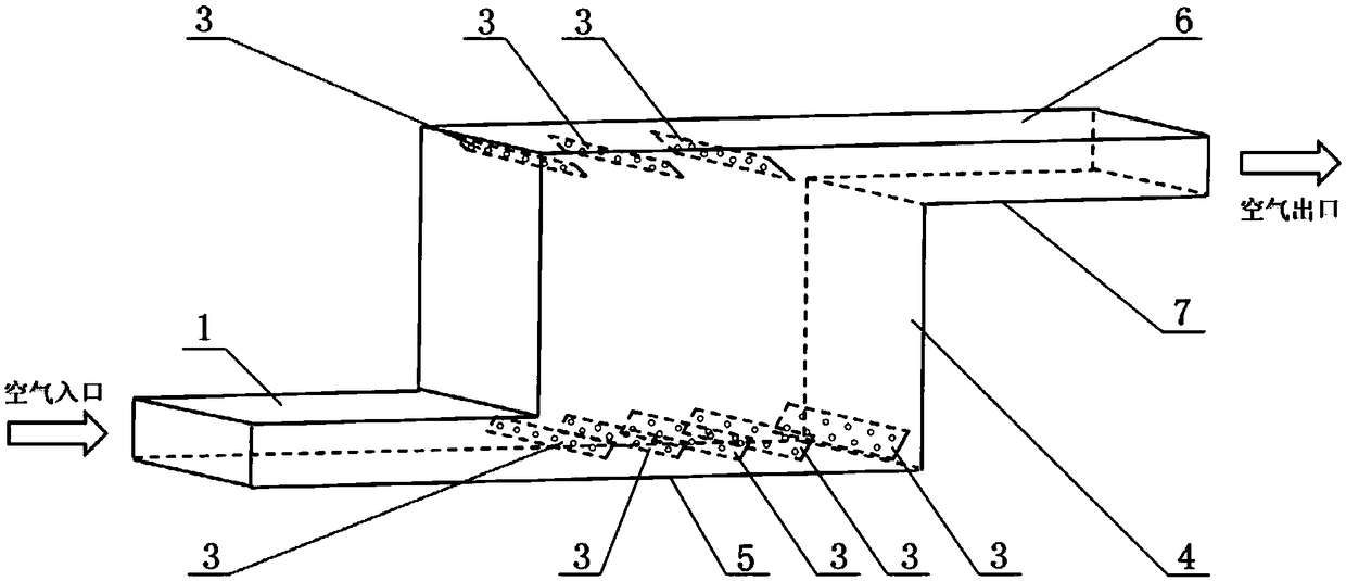
[0057] This embodiment discloses an air-cooled heat dissipation structure for a power battery pack, such as Figure 8 As shown, the air-cooled heat dissipation structure of this embodiment is basically the same as that of Embodiment 1, the difference is that the side of the collector plate 6 and the deflector 5 close to the box is provided with a shunt 3, that is, the battery box Both upper and lower sides are provided with shunt pieces, with 3 pieces on the upper side and 5 pieces on the lower side.

[0058] When the air fluid enters the air inlet flow channel 1, after passing through the interference of the first splitter on the lower side, part of the fluid is distributed between the single cells close to the inlet flow channel, and the rest of the air fluid continues to flow through the upper and lower sides of the splitter. After the flow, when it encounters the second splitter, it continues to separate part of the fluid to flow between the upper flow channels, and so on....


PUM


Abstract

The invention provides a wind cooling heat radiation structure of a power battery pack. The heat radiation structure comprises a box body, an air inlet flow passage and an air outlet flow passage, wherein the box body is used for accommodating a power battery pack; the air inlet flow passage and the air outlet flow passage are communicated with the box body and are respectively arranged on the twoopposite side surfaces of the box body; the bottom surface of the box body is a flow guide plate; the top surface of the box body is a current collecting plate; the flow guide plate and the bottom plate of the air inlet flow passage are positioned on the same plane; the current collecting plate and the top plate of the air outlet flow passage are positioned on the same plane; a flow division sheet is arranged at one side, near the box body, of the current collecting plate and/or the flow guide plate; the flow division sheet is inclined in the fluid flowing direction; the included angle between the flow division sheet and the current collecting plate and/or the flow guide plate is greater than 0 degrees but smaller than 90 degrees. The wind cooling heat radiation structure of the power battery pack is simple and reasonable; the heat radiation problem of the battery in the parallel ventilation mode can be improved at the stable state, so that the distribution of the air fluid inside thebox body provided with the power battery pack is uniform.

Description

technical field [0001] The invention relates to heat dissipation technology, in particular to an air-cooled heat dissipation structure of a power battery pack. Background technique [0002] With the continuous deepening of research on electric vehicles, the requirements for equipment equipped with electric vehicles are getting higher and higher, and the design of power batteries for electric vehicles is one of its key technologies. When the electric vehicle is working, the temperature of the power battery will gradually rise. If no timely thermal protection or heat dissipation design is adopted, the temperature of the battery will exceed its working range, which will reduce the performance of the vehicle. In severe cases, fire or explosion may occur. Therefore, it is very important to effectively control the temperature of the power battery pack. [0003] The heat dissipation methods currently used by power batteries mainly include: air cooling (air cooling or air cooling),...

Claims


Application Information

Patent Timeline
Patent Type & Authority Applications(China)
IPC IPC(8): H01M10/613H01M10/617H01M10/625H01M10/6554H01M10/6556H01M10/6563
CPCH01M10/613H01M10/617H01M10/625H01M10/6554H01M10/6556H01M10/6563Y02E60/10
Inventor 兰海侠肖永厚朱彬冯耀辉张学全贺高红郗元
Owner 辽宁比科新能源股份有限公司
Why Eureka
Try Eureka