Directional diagram reconfigurable wind-angle scanning antenna based on SSPP structure

A technology of wide-angle scanning and pattern, which is applied to the antenna, the structural form of the radiation element, the connection of the antenna grounding switch structure, etc., can solve the problem that the pattern is difficult to cover ultra-wide angles, etc., to improve end-fire performance and impedance matching , flexible switching effect

Active Publication Date: 2018-11-06
SHANGHAI JIAO TONG UNIV
View PDF7 Cites 23 Cited by
  • Summary
  • Abstract
  • Description
  • Claims
  • Application Information

AI Technical Summary

Problems solved by technology

[0004] In view of the defects in the prior art, the purpose of the present invention is to provide a wide-angle scanning antenna based on the reconfigurable

Method used


Image

  • Directional diagram reconfigurable wind-angle scanning antenna based on SSPP structure
  • Directional diagram reconfigurable wind-angle scanning antenna based on SSPP structure
  • Directional diagram reconfigurable wind-angle scanning antenna based on SSPP structure

Examples


Embodiment Construction

[0021] The present invention will be described in detail below in conjunction with specific embodiments. The following examples will help those skilled in the art to further understand the present invention, but do not limit the present invention in any form. It should be noted that those skilled in the art can make several changes and improvements without departing from the concept of the present invention. These all belong to the protection scope of the present invention.

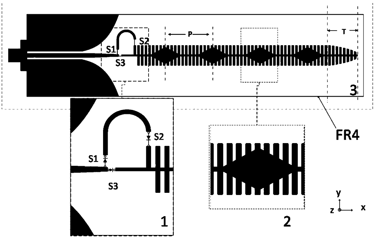
[0022] Please also see figure 1 , figure 2 , a wide-angle scanning antenna with reconfigurable pattern based on SSPP structure provided by the present invention includes: a coplanar waveguide structure composed of two trapezoidal metal sheets and a section of slender metal wire, and a symmetrical zigzag SSPP A metal transmission line, a feed selection structure composed of two metal wires welded with three switches, a quadrilateral metal modulation unit, a tapered sawtooth structure at the end, and an...


PUM


Abstract

The invention provides a directional diagram reconfigurable wind-angle scanning antenna based on a SSPP structure. The antenna comprises a coplanar waveguide structure formed by two quasi-trapezoidalmetal sheets and a segment of elongated metal lead together, symmetrical zigzag SSPP metal transmission lines, a feed selection structure formed by two paths of metal lines on which three switches arewelded, a quadrilateral metal modulation unit, an end gradient zigzag structure and an SMA connector. The SMA connector is arranged on the center of the short side of the antenna dielectric plate andused for performing radio frequency excitation for the antenna. The SMA connector is welded on one side of the coplanar waveguide structure, and one side of the coplanar waveguide structure is accessed to the feed selection structure. The feed selection structure is controlled by three changeover switches and used for selecting the current line feeding in the symmetrical zigzag SSPP metal transmission lines from the coplanar waveguide structure. The quadrilateral metal is arranged on the symmetrical zigzag SSPP metal transmission lines. The end gradient zigzag structure is used for improvingthe bandwidth and the end-fire capacity of the antenna. The problem that the present frequency scanning antenna has difficulty to realize wide-angle scanning can be solved.

Description

technical field [0001] The present invention relates to an antenna, in particular to a low-profile ultra-wide-angle scanning antenna based on an artificial surface plasmon polariton (Spoof Surface Plasmon Polariton, SSPP for short) structure. Background technique [0002] The importance of antennas in social life is growing day by day. The scanning antenna can switch the beam pointing to realize the tracking of the target. Because the frequency scanning antenna has different beam directions at different frequencies, it is widely used in radar, point-to-point communication, and satellite communication. However, the beam coverage of most frequency scanning antennas is limited, and it is impossible to achieve large-angle beam coverage. How to realize wide-angle scanning or even ultra-wide-angle scanning is a problem that researchers need to solve. [0003] The frequency scanning antenna proposed in the prior art realizes a scanning range of about 20°, but the antenna has a c...

Claims


Application Information

Patent Timeline
IPC IPC(8): H01Q1/38H01Q1/50H01Q3/00
CPCH01Q1/38H01Q1/50H01Q3/00
Inventor 耿军平庄凯杰梁仙灵王堃朱卫仁金荣洪
Owner SHANGHAI JIAO TONG UNIV
Why Eureka
Try Eureka