Polarization radiating unit permanent magnet motor

A permanent magnet motor, heat dissipation technology, applied in the direction of electromechanical devices, electrical components, mechanical equipment, etc., can solve the problems of irreversible demagnetization of permanent magnets, limit motor output, increase safety hazards, etc., to eliminate poor heat dissipation effect, increase Temperature difference, the effect of improving the heat transfer effect

Pending Publication Date: 2018-11-06
包头长安永磁电机有限公司
View PDF0 Cites 15 Cited by
  • Summary
  • Abstract
  • Description
  • Claims
  • Application Information

AI Technical Summary

Problems solved by technology

However, the permanent magnet is installed on the rotor, and it is difficult to dissipate heat. The temperature rise caused may cause irreversible demagnetization of the permanent magnet, which limits the output of the motor and increases the potential safety hazard.
[0003] The traditional ventilation and heat dissipation structure of permanent magnet motors uses fans to provide power for air flow, resulting in waste of electric energy

Method used


Image

  • Polarization radiating unit permanent magnet motor
  • Polarization radiating unit permanent magnet motor
  • Polarization radiating unit permanent magnet motor

Examples


Embodiment 1

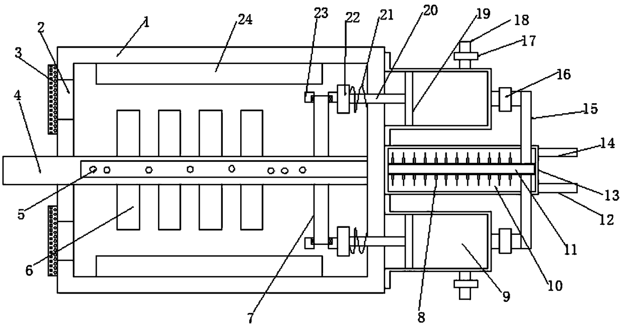
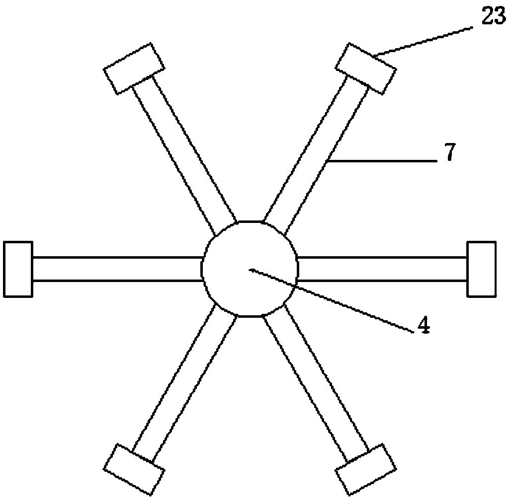
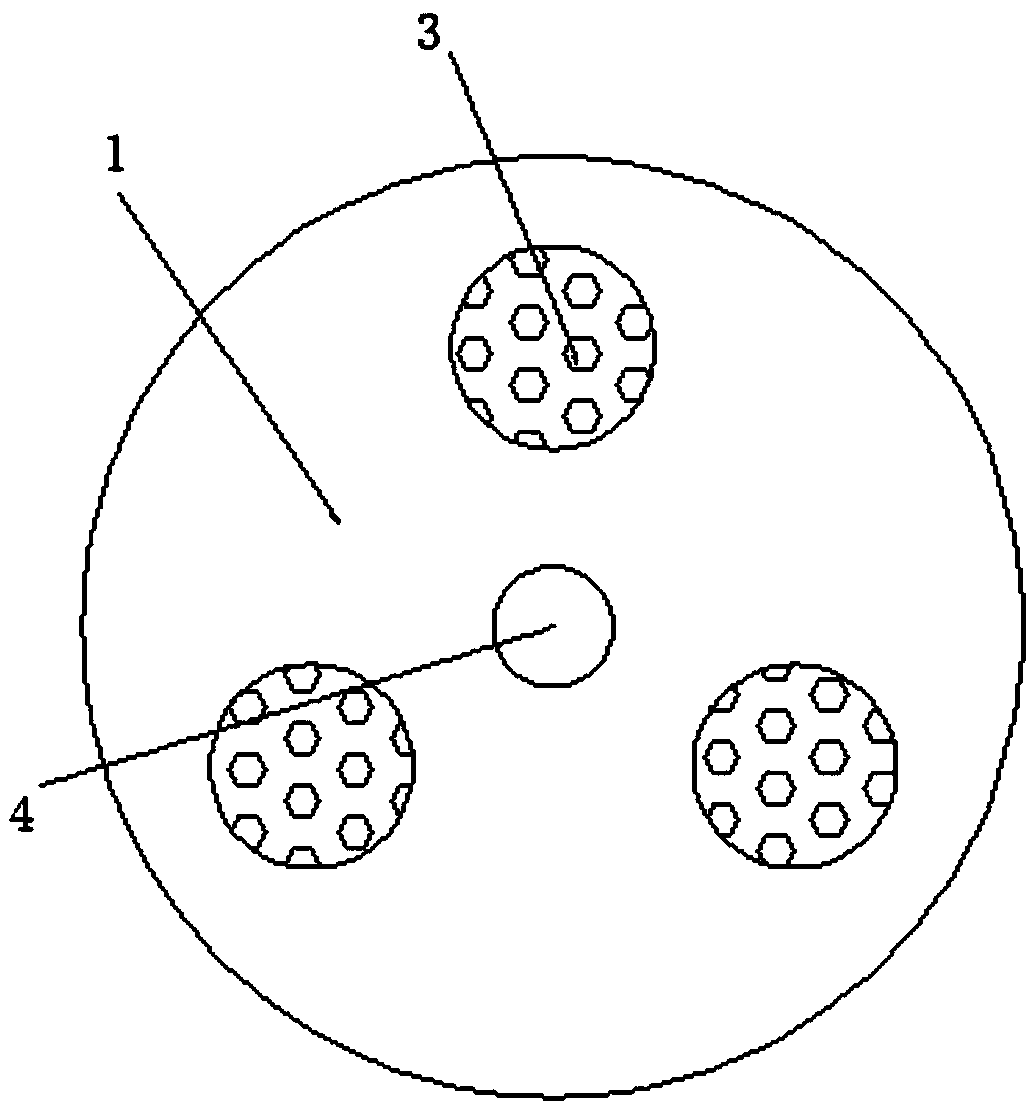
[0019] see Figure 1~3 , in the embodiment of the present invention, a polarized heat dissipation unit permanent magnet motor includes a casing 1, a rotating shaft 4 is provided in the middle of the casing 1, and an air guiding cavity is arranged inside the rotating shaft 4, where the air guiding cavity is located. The surface of the rotating shaft 4 is provided with an air injection hole 5, the surface of the rotating shaft 4 is provided with a rotor 6, the inner wall of the casing 1 is fixed with a stator 24 corresponding to the rotor 6, and the right end of the rotating shaft 4 is distributed with a number of polarization Rod 7, the polarizing wheel 23 is arranged at the end of the polarizing rod 7, and a rotating bearing is arranged between the polarizing wheel 23 and the polarizing rod 7, and a plurality of exhaust ports 2 are distributed on the left end of the casing 1, and the exhaust ports 2 The number is three, the outer surface of the exhaust port 2 is provided with ...

Embodiment 2

[0021] The difference from Embodiment 1 is that several heat dissipation fins 8 are provided outside the heat exchange air duct 11, thereby increasing the heat dissipation area and improving the heat dissipation effect.


PUM


Abstract

The invention discloses a polarization radiating unit permanent magnet motor which comprises a case, wherein a rotating shaft is arranged at a middle position of the case; an air guide chamber is formed inside the rotating shaft; a gas orifice is formed in the surface of the rotating shaft on which the air guide chamber is positioned; a rotor is arranged on the surface of the rotating shaft; a stator corresponding to the rotor is fixed on the inner wall of the case; an air compression heat exchange mechanism for continuously replacing, compressing and cooling air inside the case is arranged atthe right end of the rotating shaft. The polarization radiating unit permanent magnet motor disclosed by the invention is simple and reasonable in structure, and the operation of the air compressionmechanism is driven by taking the rotating shaft as driving force, so that the air is compressed, the temperature of the air is increased, the temperature difference with heat exchange liquid is increased, and the heat exchange effect. Then, the compressed air is ejected out via the gas orifice, and the compressed air outwards expands to reduce the temperature, so that the heat dissipation effectof the case is improved. Moreover, due to the rotary gas orifice, heat dissipation on the inner wall of the case is uniform, and the practicality is high.

Description

technical field [0001] The invention relates to the technical field of motor equipment, in particular to a polarization heat dissipation unit permanent magnet motor. Background technique [0002] Permanent magnet motors have the advantages of high efficiency, high power density, large power factor, large starting torque, wide speed range, etc., and have gradually replaced induction motors and switched reluctance motors, and are increasingly being used in many fields of industrial production and daily life. Wide range of applications. However, since the permanent magnet is installed on the rotor, it is difficult to dissipate heat. The temperature rise caused by the permanent magnet may cause irreversible demagnetization of the permanent magnet, which limits the output of the motor and increases the potential safety hazard. [0003] The traditional ventilation and heat dissipation structure of permanent magnet motors uses fans to provide power for air flow, resulting in waste...

Claims


Application Information

Patent Timeline
Patent Type & Authority Applications(China)
IPC IPC(8): H02K9/00H02K5/20H02K9/04F04B35/04
CPCH02K9/00F04B35/04H02K5/20H02K9/04
Inventor 苏锦智张继鹏付荣华刘慧博
Owner 包头长安永磁电机有限公司
Why Eureka
Try Eureka