
Precise and fine wire feeding machine

A wire feeder and fine technology, applied in arc welding equipment, manufacturing tools, welding equipment, etc., can solve the problems of inconvenient wire changing, low applicability, narrow wire feeding speed range, etc., to save assembly space, High applicability and easy adjustment

Pending Publication Date: 2018-11-09
NAT INST CORP OF ADDITIVE MFG XIAN
View PDF13 Cites 6 Cited by
  • Summary
  • Abstract
  • Description
  • Claims
  • Application Information

AI Technical Summary

Problems solved by technology

[0004] With the above-mentioned structure, although the delivery requirements of wires with different diameters are met to a certain extent, this wire feeder drives two sets of extrusion wheels to transfer wires through a motor. The structure is complicated, and the speed of wire transfer is controlled by the motor itself. The speed is determined by the speed, so that the speed range of wire feeding is narrowed, so that its applicability is reduced, and this structure has problems such as inconvenient wire replacement and inconvenient adjustment of the pressing mechanism.

Method used


Image

  • Precise and fine wire feeding machine
  • Precise and fine wire feeding machine
  • Precise and fine wire feeding machine

Examples


Embodiment Construction

[0032] The present invention will be further elaborated below in conjunction with the accompanying drawings.

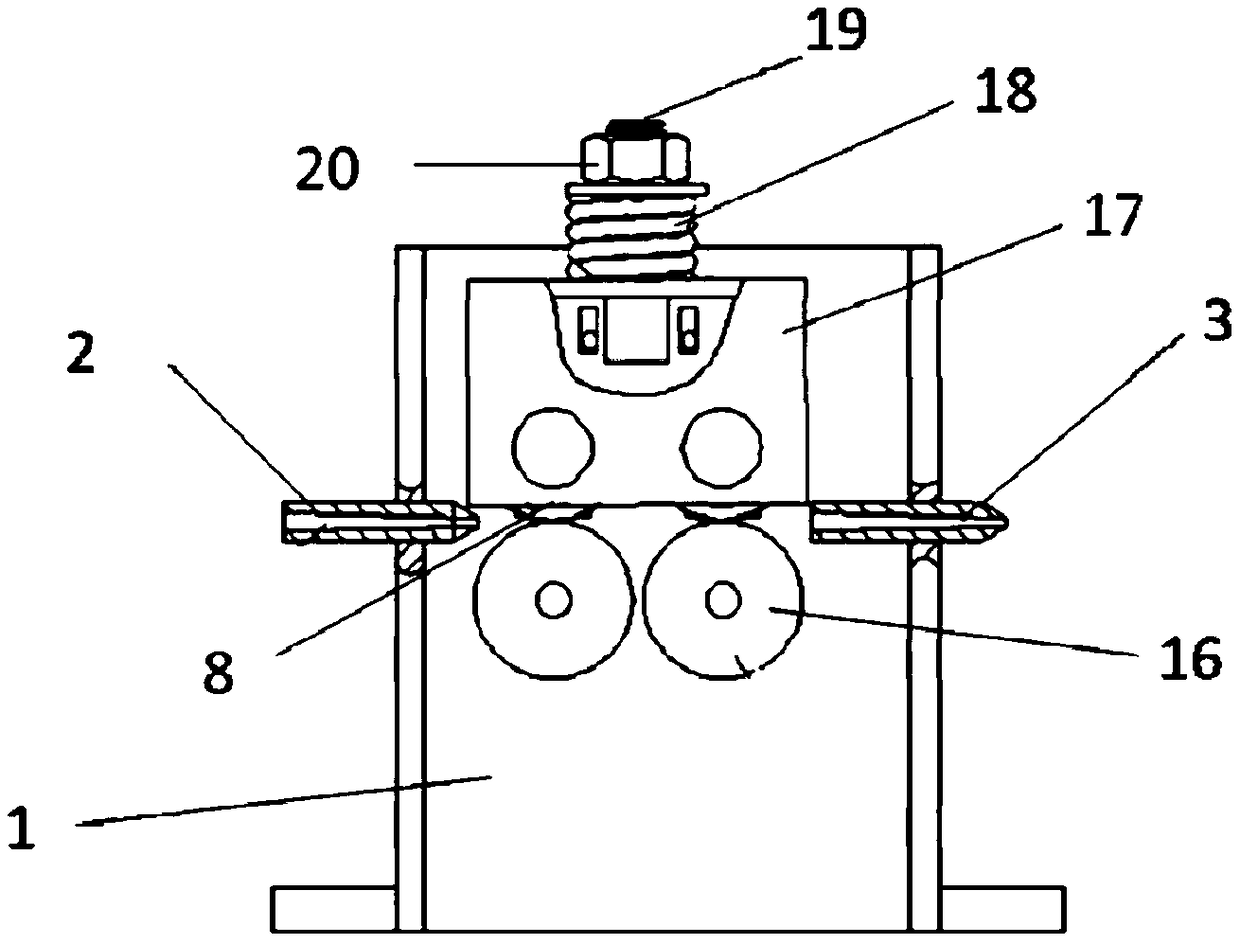
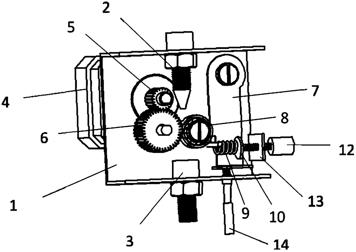
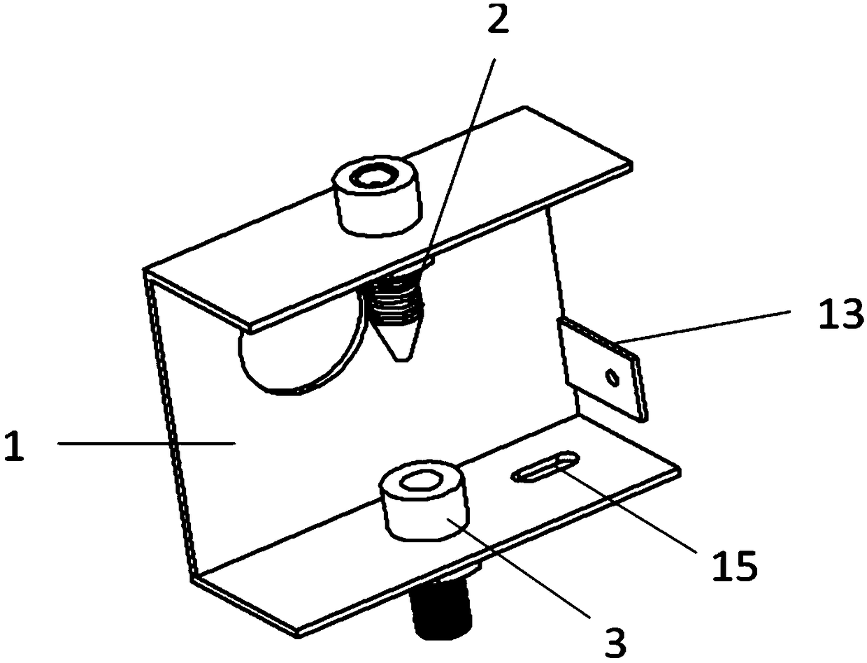
[0033] Such as figure 2 , image 3 and Figure 5 As shown, the precision micro-wire feeder of the present invention has a frame groove 1, a wire inlet conduit 2, a wire outlet conduit 3 and a pressing mechanism; A wire outlet conduit 3 is provided on the side wall, and the wire inlet conduit 2 and the wire outlet conduit 3 are located on the same straight line to form a wire feeding path; the pressing mechanism is installed in the frame groove 1 and is located on one side of the wire feeding path; It includes a transmission mechanism arranged on the other side of the wire feeding path; the transmission mechanism includes a motor 4, a driving wheel 5 and a driven wheel 6; the motor 4 is fixedly installed on the frame slot 1, and the output shaft of the motor 4 is installed on the The wheel 5 and the driven wheel 6 are fixedly installed in the frame groove 1 and mes...


PUM


Abstract

The invention provides a precise and fine wire feeding machine which comprises a machine frame groove, a wire feeding guide tube, a wire discharging guide tube and a pressing mechanism. The wire feeding guide tube is arranged on one side wall of the machine frame groove, the wire discharging guide tube is arranged on the other side wall of the machine frame groove, and the wire feeding guide tubeand the wire discharging guide tube are located in the same straight line to form a wire feeding route. The pressing mechanism is mounted in the machine frame groove and located on one side of the wire feeding route. The precise and fine wire feeding machine further comprises a transmission mechanism arranged on the other side of the wire feeding route. The transmission mechanism comprises a motor, a driving wheel and a driven wheel. The motor is fixedly mounted on the machine rack groove, and an output shaft of the motor is provided with the driving wheel. The driven wheel is fixedly mountedin the machine frame groove and is engaged with the driving wheel. The driving wheel and the pressing mechanism are matched to achieve wire feeding. The driving wheel is engaged with the driving wheelwith different tooth number, the different transmission ratio requirements can be met, and different wire feeding speed is obtained.

Description

technical field [0001] The invention relates to the field of wire feeding equipment, in particular to a precision fine wire feeding machine. Background technique [0002] At present, in the field of metal welding, connector welding in the electrical and electronic industry, non-contact welding inside small relays, non-contact welding of silver contacts of AC contactors, leakage protectors, and bulb filaments, high-voltage copper tubes in the refrigeration industry Welding, welding between various components in the jewelry industry and welding in the metal jewelry and metal crafts metal manufacturing industry all require high precision and high quality, so there is a higher requirement for the wire feeder in welding. However, the traditional welding mainly uses welding wire above Φ0.8mm, which makes the wire feeder larger in size and severely limits its scope of application. [0003] For this reason, many efforts have been made to improve the performance of wire feeders. Ch...

Claims


Application Information

Patent Timeline
Patent Type & Authority Applications(China)
IPC IPC(8): B23K9/133
CPCB23K9/133
Inventor 王万军闫雪萍王强李波波李玉强施建旭冀千瑜任晓飞
Owner NAT INST CORP OF ADDITIVE MFG XIAN
Learn More