A method and device for powering off a battery management system
A technology of a battery management system and an electrical method, which is applied in the field of power-off methods and devices of the battery management system, and can solve problems such as insufficient cooperation between VCU and BMS, potential safety hazards, etc.
- Summary
- Abstract
- Description
- Claims
- Application Information
AI Technical Summary
Problems solved by technology
Method used
Image
Examples
Embodiment 1
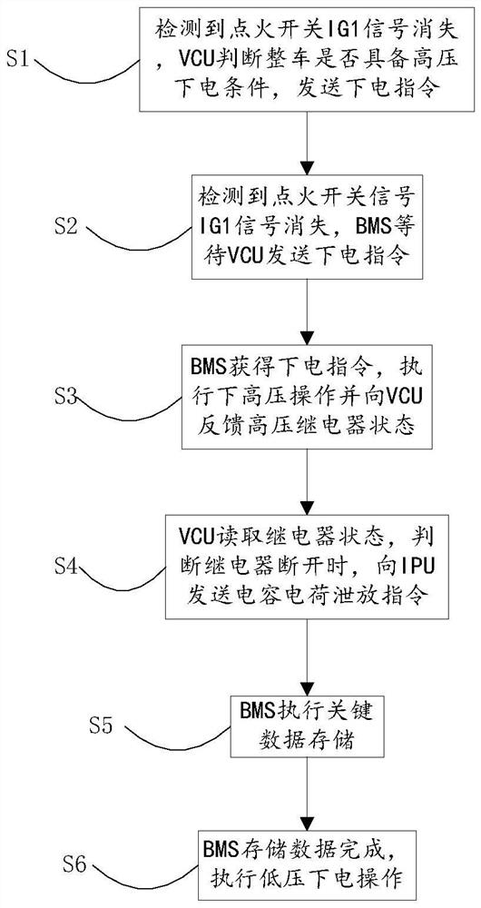
[0048] An embodiment of the present invention provides a method for powering off a battery management system, such as figure 1 As shown, the method includes:
[0049] S1. Detecting that the key signal IG1 disappears, the VCU (vehicle controller) judges whether the vehicle has the high-voltage power-off condition, and sends a power-off command;
[0050] S2. Detecting that the key signal IG1 disappears, the BMS (battery management system) waits for the VCU (vehicle controller) to send a power-off command;
[0051] S3. The BMS (battery management system) obtains the power-off command, executes the high-voltage operation and feeds back the status of the high-voltage relay to the VCU (vehicle controller);
[0052] S4. The VCU (vehicle controller) reads the status of the relay, and when it judges that the relay is disconnected, sends a capacitive charge discharge command to the IPU (integrated combined power unit);
[0053] S5. BMS (Battery Management System) performs key data sto...
Embodiment 2
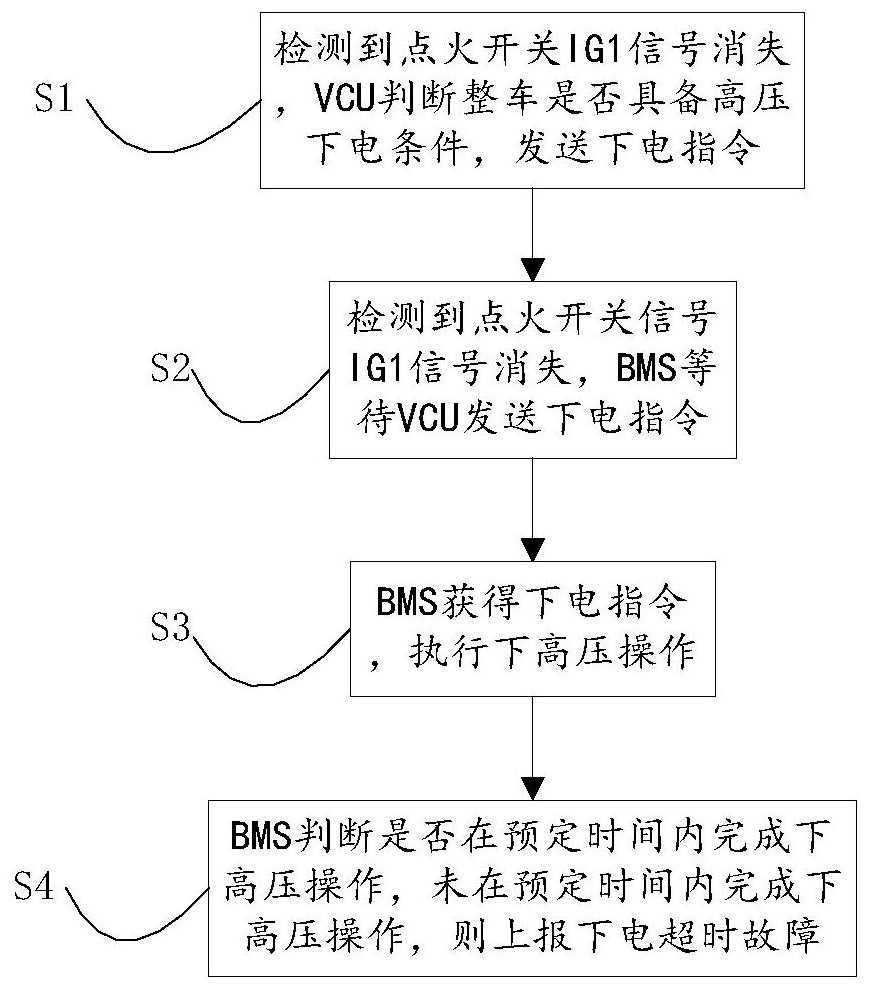
[0065] The embodiment of the present invention proposes a method for detecting a power-off timeout fault when the battery management system is powered off, such as image 3 As shown, the method includes:
[0066] S1. Detecting that the key signal IG1 disappears, the VCU (vehicle controller) judges whether the vehicle has the high-voltage power-off condition, and sends a power-off command;
[0067] S2. Detecting that the key signal IG1 disappears, the BMS (battery management system) waits for the VCU (vehicle controller) to send a power-off command;
[0068] S3. The BMS (battery management system) receives the power-off command and executes the high-voltage operation.
[0069] S4. The BMS (battery management system) judges whether the high-voltage operation is completed within the predetermined time, and if the high-voltage operation is not completed within the predetermined time, it will report a power-off overtime fault.
[0070] Specifically, until the BMS (battery managem...
Embodiment 3
[0075] The embodiment of the present invention proposes a method for detecting the fault that the relay is not disconnected when the battery management system is powered off, such as Figure 4 As shown, the method includes:
[0076] S1. Detecting that the key signal IG1 disappears, the VCU (vehicle controller) judges whether the vehicle has the high-voltage power-off condition, and sends a power-off command;
[0077] S2. Detecting that the key signal IG1 disappears, the BMS (battery management system) waits for the VCU (vehicle controller) to send a power-off command;
[0078] S3. The BMS (battery management system) obtains the power-off command and executes the high-voltage operation;
[0079] S4. The BMS (battery management system) fails to complete the high-voltage power-off operation within the predetermined time, and reports a power-off overtime fault. The high voltage relay is not disconnected;
[0080] S5. The VCU (vehicle controller) reads the status of the relay, j...
PUM
 Abstract
Description
Claims
Application Information
 - R&D
- Intellectual Property
- Life Sciences
- Materials
- Tech Scout
- Unparalleled Data Quality
- Higher Quality Content
- 60% Fewer Hallucinations
Browse by: Latest US Patents, China's latest patents, Technical Efficacy Thesaurus, Application Domain, Technology Topic, Popular Technical Reports.
© 2025 PatSnap. All rights reserved.Legal|Privacy policy|Modern Slavery Act Transparency Statement|Sitemap|About US| Contact US: help@patsnap.com


