Hidden silent quick exhaust valve, silent air cylinder and silent numerical control gang drill device

A kind of exhaust valve, hidden technology, applied in the direction of the valve device, the device for absorbing fluid energy of the valve, fixed drilling machine, etc., can solve the problems of long exhaust path, complex overall structure of the cylinder, and slow retraction of the tool rod. Achieve the effects of reducing production and production costs, broad market prospects, and improving processing efficiency

Pending Publication Date: 2018-11-09
常州市翰琪电机有限公司
View PDF2 Cites 0 Cited by
  • Summary
  • Abstract
  • Description
  • Claims
  • Application Information

AI Technical Summary

Problems solved by technology

However, the structure of this type of cylinder is relatively simple, and there is no air return mechanism itself. It is necessary to install an air return mechanism in the cylinder body, or use an external method (solenoid valve or external quick-discharge valve) to return air, and the solenoid valve exhausts. The disadvantages are 1. The exhaust path is long and the stroke is long; 2. As a moving part, the solenoid valve is exposed to a lot of moisture in the compressed air, which is prone to blockage of the cylinder push rod, which affects the exhaust efficiency and causes the knife rod to retract slowly. It affects the safety of CNC row drilling, drilling and tool setting processing, which greatly increases the production cost of the cylinder and complicates the overall structure of the cylinder.

Method used


Image

  • Hidden silent quick exhaust valve, silent air cylinder and silent numerical control gang drill device
  • Hidden silent quick exhaust valve, silent air cylinder and silent numerical control gang drill device
  • Hidden silent quick exhaust valve, silent air cylinder and silent numerical control gang drill device

Examples


Embodiment Construction

[0031] The preferred embodiments of the present invention will be described in detail below in conjunction with the accompanying drawings, so that the advantages and features of the present invention can be more easily understood by those skilled in the art, so as to define the protection scope of the present invention more clearly. The directional terms mentioned in the present invention, such as "up", "down", "front", "back", "left", "right", "top", "bottom", etc., are only for reference to the attached drawings. direction. Therefore, the directional terms used are used to illustrate and understand the present invention, but not to limit the present invention.

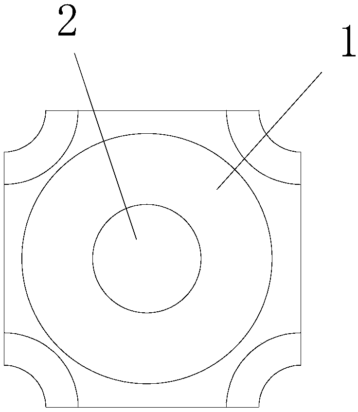
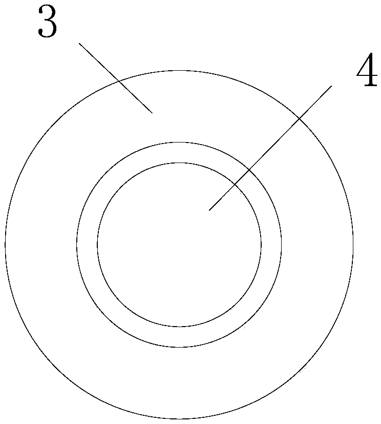
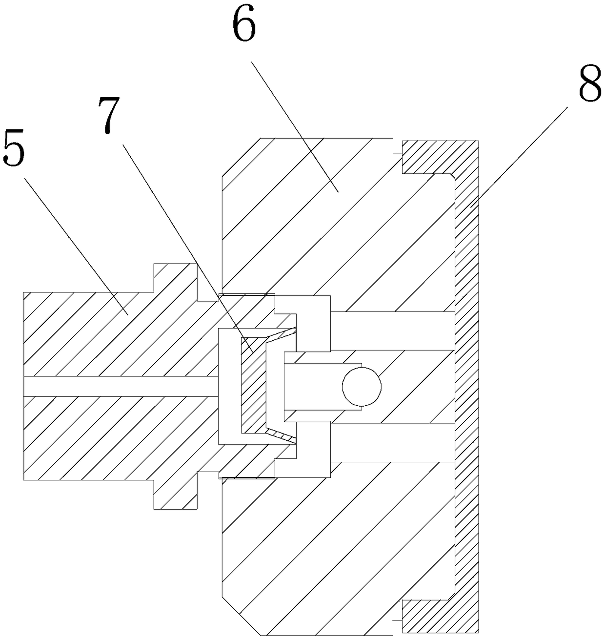
[0032] Such as image 3 A concealed silent quick exhaust valve for numerically controlled drilling as shown, including a valve body 6 and a joint 5, the joint 5 is provided with an air inlet, and the valve body 6 An air outlet is provided, and a guide lock washer 7 that can close the exhaust hole through the intake...


PUM


Abstract

The invention relates to a hidden silent quick exhaust valve of a numerical control gang drill. The hidden silent quick exhaust valve comprises a valve body and a connector, the connector is providedwith an air inlet hole, an air outlet hole is formed in the valve body, the air inlet hole communicates with the air outlet hole, a ventilated air exhausting groove is formed in the valve body, the air outlet hole is formed in the ventilated air exhausting groove, an exhausting boss extending upwards is arranged in the ventilated air exhausting groove and is internally provided with an exhaustinghole communicating with the ventilated air exhausting groove, the exhausting hole extends outside the valve body, an air inlet groove is formed in the connector and communicates with the air inlet hole, and a guide locking gasket is sleeved with the air inlet groove. According to the hidden silent quick exhaust valve of the numerical control gang drill, air inlet and quick exhausting can be achieved without an electromagnetic valve, so that quick knife feeding cutting, quick knife retreating and high-speed high-efficiency cutting can be achieved through a gang drill main shaft, the productionand manufacturing cost is reduced, and the machining efficiency is improved by 2-3 times; and meanwhile, a buffer silencing mat is arranged, and therefore noise in the production process is greatly reduced.

Description

technical field [0001] The invention relates to the technical field of numerical control drilling, in particular to a hidden silent quick exhaust valve for numerical control drilling, a silent cylinder equipped with a hidden silent quick exhaust valve and a machine equipped with a hidden silent quick exhaust valve. Silent CNC drilling device. Background technique [0002] Today, with the popularization of information technology, the deep integration of traditional industry and electronic technology informatization is the only way for enterprise development and transformation. The efficient, precise and flexible customized production of CNC technology is the envy of the original non-NC industry. As one of the eight sub-categories of industry, the woodworking industry is partial to people's livelihood. It has always been a neglected sector in industrial development. The popularization and penetration of numerical control technology has quickly turned the entire industry into a...

Claims


Application Information

Patent Timeline
IPC IPC(8): F16K11/044F16K47/00B27C3/04
CPCF16K11/044F16K47/00B27C3/04
Inventor 钱程蒋伟钱翰琪
Owner 常州市翰琪电机有限公司
Why Eureka
Try Eureka