Battery overcharging prevention device for new energy automobile
A new energy vehicle, battery charging technology, applied in battery circuit devices, battery overcharge protection, circuit devices, etc., can solve problems such as battery overcharge, affecting battery life, lack of battery, etc., to achieve the effect of ensuring stability
- Summary
- Abstract
- Description
- Claims
- Application Information
AI Technical Summary
Problems solved by technology
Method used
Image
Examples
Embodiment 1
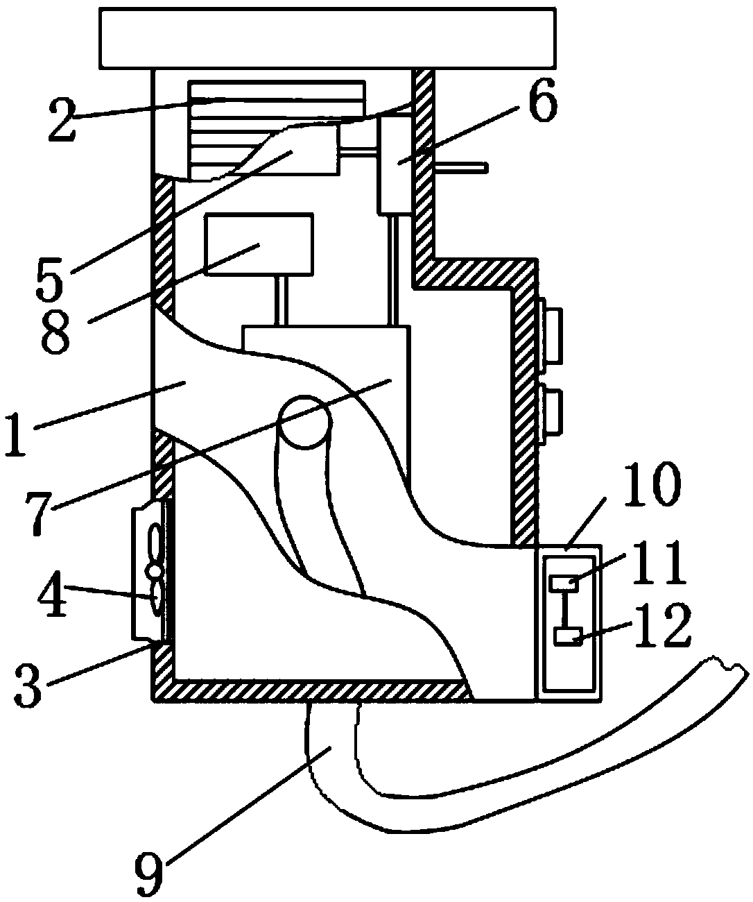
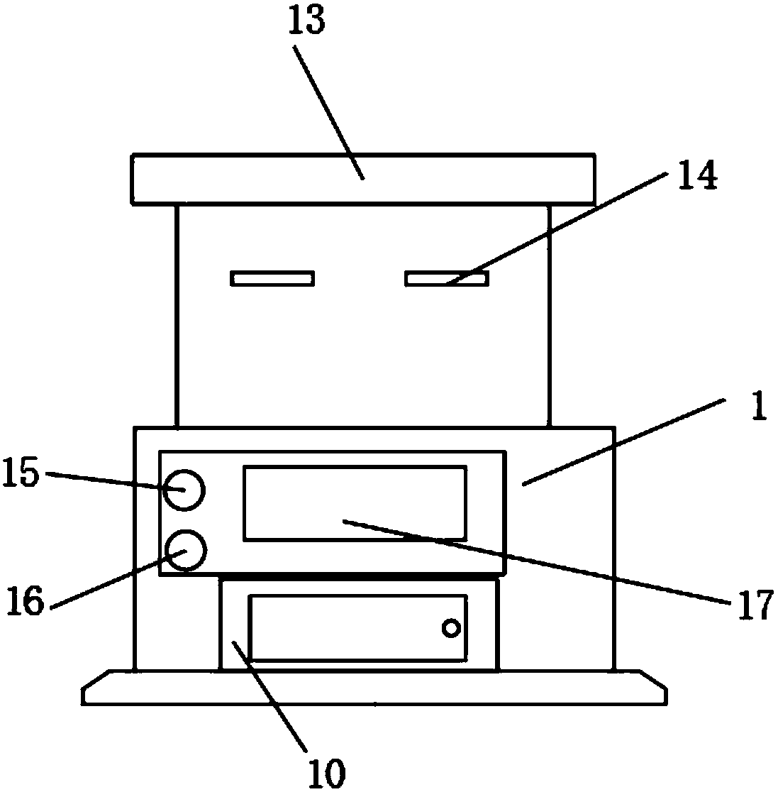
[0023] Embodiment one: refer to Figure 1-4 , a battery overcharging prevention device for a new energy vehicle, comprising a charging pile 1, a sampling circuit 5 is arranged inside the charging pile 1, the sampling circuit 5 is connected to a switching circuit 6 through a wire, and the switching circuit 6 is connected to a charging control through a wire circuit 7, and the charging control circuit 7 is connected with a battery charging voltage detection circuit 8 through wires, wherein the switch circuit 6, the charging control circuit 7, and the battery charging voltage detection circuit 8 are all located inside the charging pile 1, and on the surface wall of the charging pile 1 A wire 9 is connected, an electric control box 10 is fixed on the front surface of the charging pile 1, a signal receiver 11 and a PLC controller 12 are fixed inside the electric control box 10, a protective cover 13 is fixed on the top bolt of the charging pile 1, and the front of the charging pile ...
Embodiment 2
[0024] Embodiment two: refer to figure 1 There is an air inlet 2 on the surface wall of the charging pile 1, and an air outlet 3 is opened on the bottom of the back of the charging pile 1, and the inside of the air outlet 3 is fixed with an exhaust fan 4 through a fixing frame, the air inlet 2 and the outlet The setting of the air port 3 is used for heat dissipation of the charging pile 1.
Embodiment 3
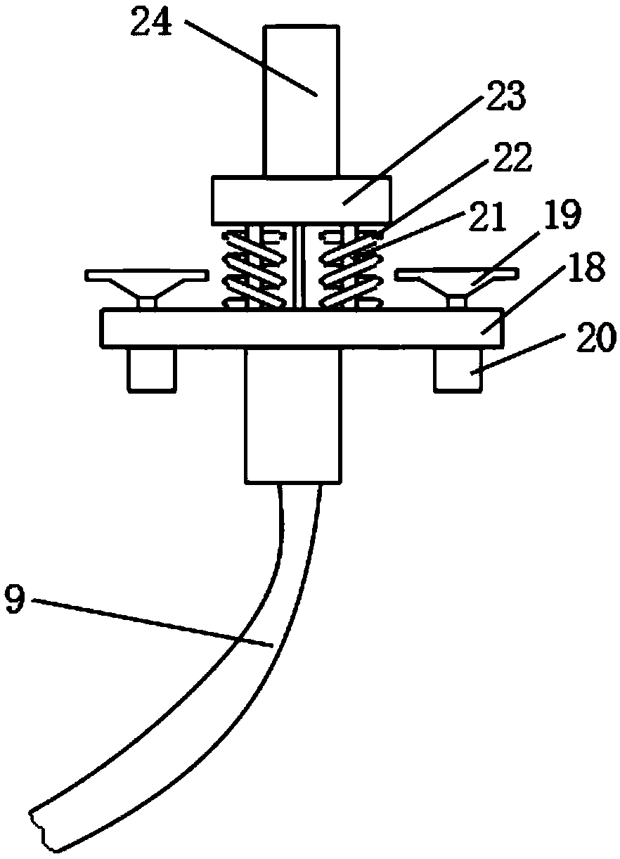
[0025] Embodiment three: refer to image 3 , the charging base 23 is fixed with a fixed base 18 through an electric push rod 21, and a spring 22 is sleeved on the electric push rod 21, a suction cup 19 is arranged on one side of the fixed base 18, and a fixed surface is fixed on the other side of the fixed base 18. There are micro air pumps 20 used in conjunction with the suction cup 19. There are four electric push rods 21 in total, and the four electric push rods 21 are symmetrically arranged at the four corners of the fixing seat 18. The electric push rods 21 are used to drive the charging plug 24 up and down. Move, used to automatically pull out the charging plug 24 from the charging hole, stop battery charging, the fixed seat 18 is used to fix the charging stand 23, to ensure the stability of the charging plug 24 on the charging stand 23 and the charging hole plugging, the suction cup 19 is used Suction and fixation on the fixed seat 18.
PUM
 Abstract
Description
Claims
Application Information
 - R&D Engineer
- R&D Manager
- IP Professional
- Industry Leading Data Capabilities
- Powerful AI technology
- Patent DNA Extraction
Browse by: Latest US Patents, China's latest patents, Technical Efficacy Thesaurus, Application Domain, Technology Topic, Popular Technical Reports.
© 2024 PatSnap. All rights reserved.Legal|Privacy policy|Modern Slavery Act Transparency Statement|Sitemap|About US| Contact US: help@patsnap.com


