Reagent detecting tube and assembly thereof
A detection tube and reagent technology, applied in the field of detection tubes, can solve the problems that non-professionals cannot carry out detection, detection work cannot be carried out, and there are many types and quantities of containers, so as to achieve accurate and reliable detection results, improve experimental accuracy, and simple structure. Effect
- Summary
- Abstract
- Description
- Claims
- Application Information
AI Technical Summary
Problems solved by technology
Method used
Image
Examples
Embodiment 1
[0053] Refer to attached figure 1As shown, the reagent detection tube of this embodiment includes a tubular body 2 and a cover 1 that fits and seals with it.
[0054] The inner wall of the bottom end of the tubular body 2 is provided with an internal thread 5, and an isolation film 6 for sealing the bottom end of the tubular body 2 is arranged above the internal thread 5, and a housing for the tubular body 2 is formed above the isolation film 6. cavity. The upper part of the tubular body 2 is provided with an external thread 4 matching the internal thread 5 , and the length of the external thread 4 is greater than the length from the bottom end of the tubular body to the isolation membrane. In this way, when the two detection tubes are connected end to end, a pair of sealing and matching connection pairs are formed by the external thread 4 of the lower tubular body and the internal thread 5 of the upper tubular body. The isolation membrane 6 of the upper tubular body can be ...
Embodiment 2
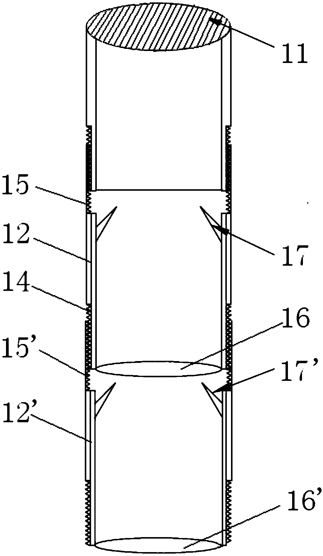
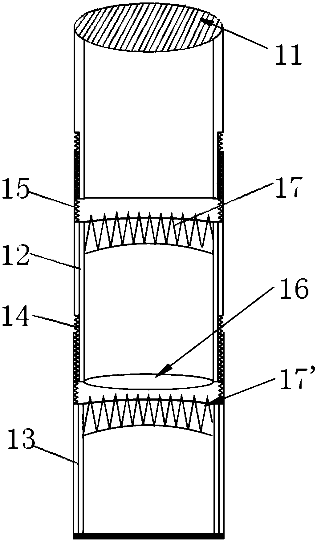
[0064] The difference between the second embodiment and the first embodiment is that the outer wall of the bottom end of the tubular body 12 is provided with an external thread 14 , and the inner wall of the top end of the tubular body 12 is provided with an internal thread 15 . The isolation membrane 16 is disposed at the bottom of the tubular body 12 , and the upper inner wall of the tubular body 12 is provided with an upwardly protruding spike 17 . The number of the spikes 17 can be set as required, and the upward angle can also be set as obliquely upward as required. as attached figure 2 Only two relative upward spikes 17 are set on the inner wall of the tubular body; as attached image 3 A circle of upward spikes 17 is set on the inner wall circumference of the tubular body, both of which can realize that when two tubular bodies are connected end to end, the spikes of the lower tubular body pierce the isolation film of the upper tubular body to realize the accommodation...
Embodiment 3
[0069] as attached Figure 5 and 6 As shown, the difference between the third embodiment and the second embodiment above is that the circumferential side wall or part of the side wall of the lower part of the tubular body 22 adopts the bellows elastic structure 20, and the interior of the tubular body 22 is provided with a downward protruding Spikes 28, the spikes 28 are set in the tubular body 22 through the connecting rod 29, when the two tubular bodies are connected, the bellows elastic structure 20 is pressed, so that the spikes 28 are driven to pierce the isolation membrane 26, and two tubular bodies up and down are realized. The connection of the body accommodating cavity.
[0070] Specifically: refer to the attached Figure 5 and 6 As shown, the tubular body 22 and the tubular body 22' have the same structure. After connecting the tubular body 22 and the tubular body 22' end to end, by pressing the bellows elastic structure 20, the side wall of the tubular body 22 wi...
PUM
| Property | Measurement | Unit |
|---|---|---|
| Thickness | aaaaa | aaaaa |
Abstract
Description
Claims
Application Information
 - R&D
- Intellectual Property
- Life Sciences
- Materials
- Tech Scout
- Unparalleled Data Quality
- Higher Quality Content
- 60% Fewer Hallucinations
Browse by: Latest US Patents, China's latest patents, Technical Efficacy Thesaurus, Application Domain, Technology Topic, Popular Technical Reports.
© 2025 PatSnap. All rights reserved.Legal|Privacy policy|Modern Slavery Act Transparency Statement|Sitemap|About US| Contact US: help@patsnap.com


