
Three-roller grinding machine

A three-roller mill and push mechanism technology, applied in grain processing and other directions, can solve the problem of accumulation in the main funnel, and achieve the effects of facilitating maintenance, improving product quality, and avoiding wear and tear.

Active Publication Date: 2018-11-13
YANCHENG SHENYUAN PLASTIC
View PDF16 Cites 0 Cited by
  • Summary
  • Abstract
  • Description
  • Claims
  • Application Information

AI Technical Summary

Problems solved by technology

[0005] However, for viscous slurry materials, using the angle formed by the side wall of the diverted channel and the side wall of the main funnel to separate the formed paint, it is very likely that the paint will be blocked and cannot continue to go out along the main funnel. Material and separation work, and build-up phenomenon on the main funnel

Method used


Image

  • Three-roller grinding machine
  • Three-roller grinding machine
  • Three-roller grinding machine

Examples


Embodiment

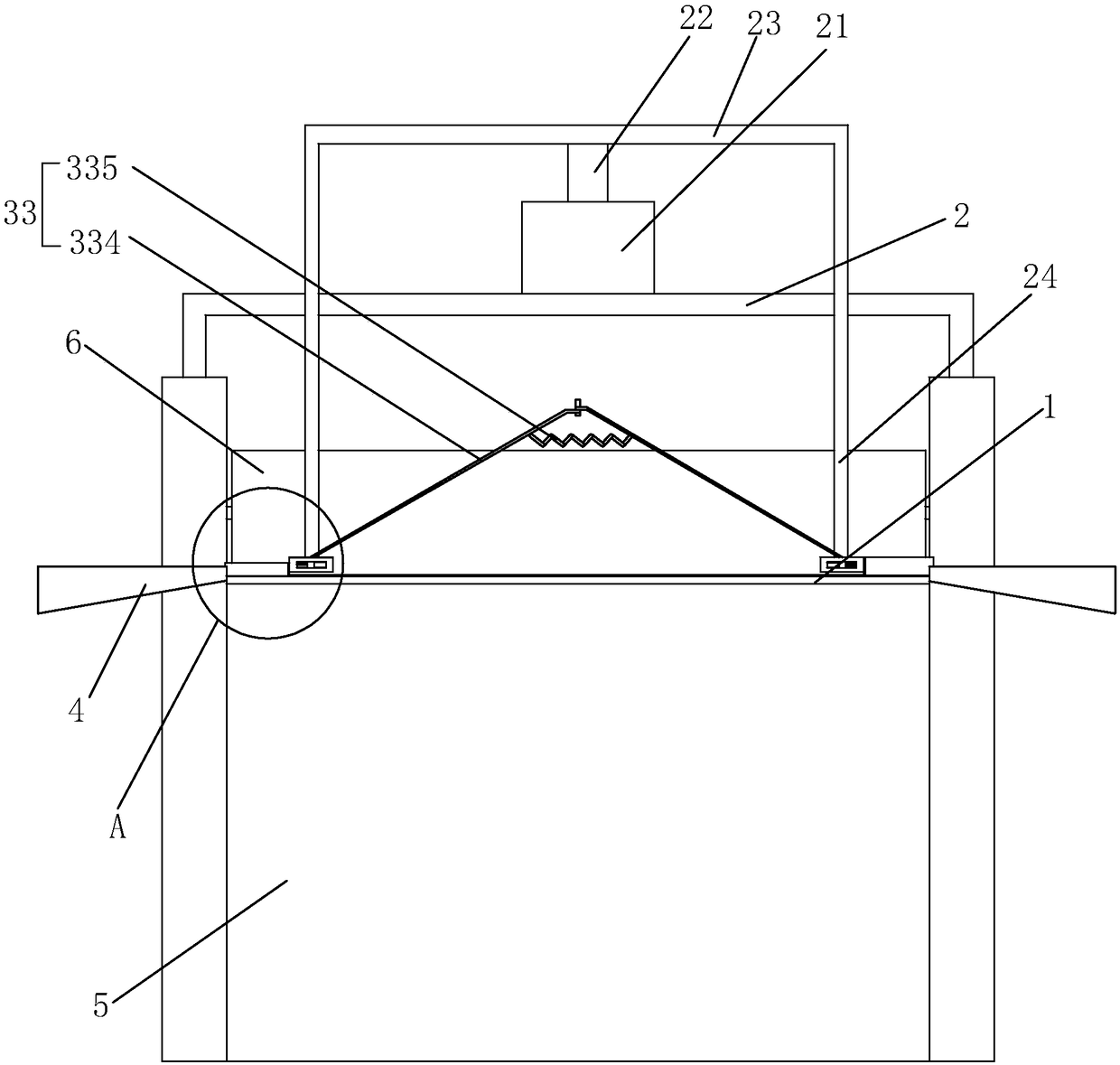
[0038]Embodiment: a kind of three-roll grinder, comprise frame 5, be arranged on the transmission system in frame 5, and be arranged on three roller shafts 6 that are controlled to rotate by transmission system on frame 5, these three roller shafts 6 are respectively The rear roller, the middle roller and the front roller, the rear roller is the feeding end for the material to be put in, the front roller is the output end of the material, and the outlet of the front roller is provided with a main funnel 1 matching the outlet. The material to be ground is placed at the feed end of the rear roller, and the transmission of the material is realized through the transmission between the roller shafts 6. During the transmission process, the mutual extrusion between the roller shafts 6 and the friction at different speeds are achieved. Grinding effect, there is also a scraper at the outlet of the front roller to scrape off the material that has been ground into slurry, so that the slur...

specific Embodiment approach

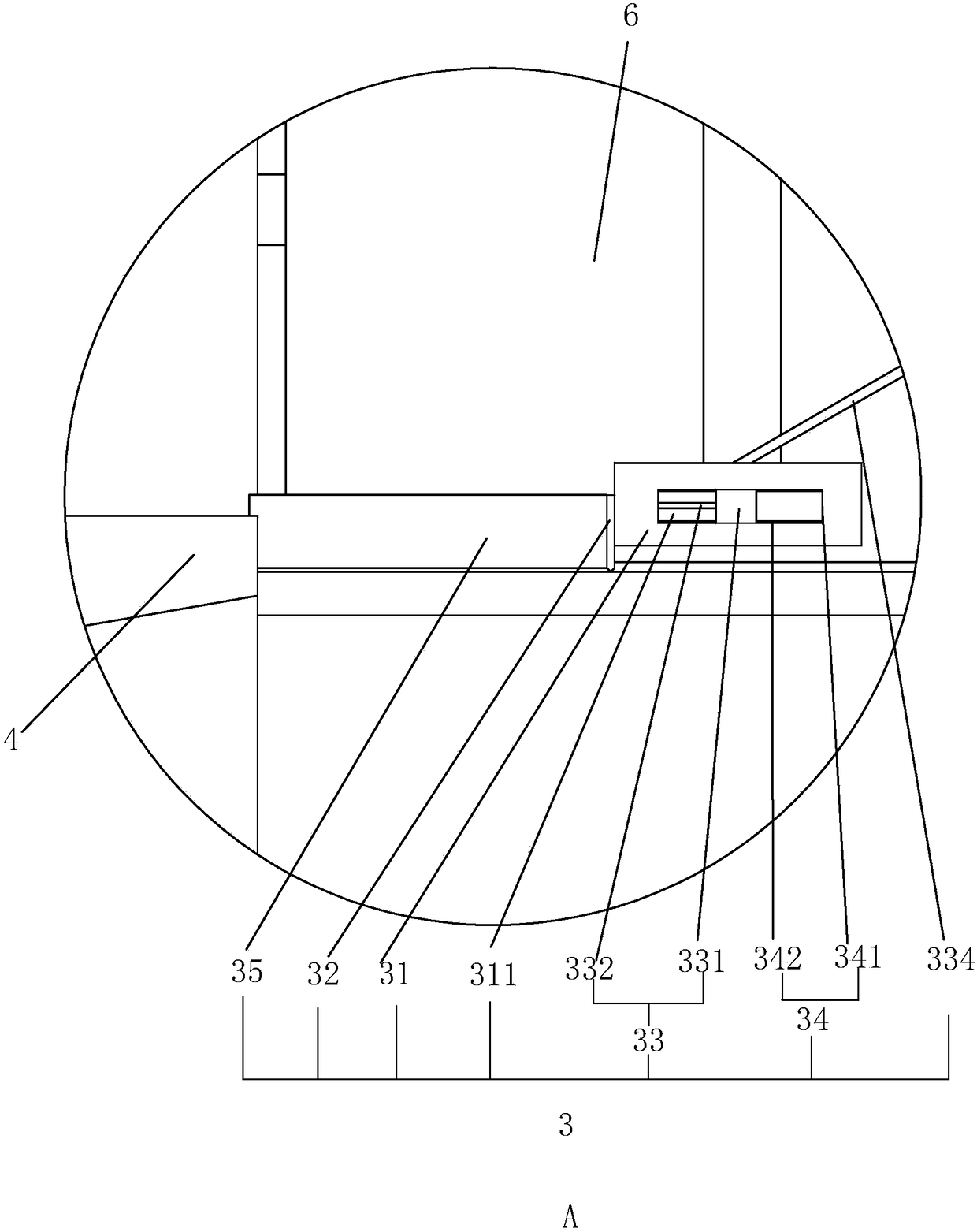
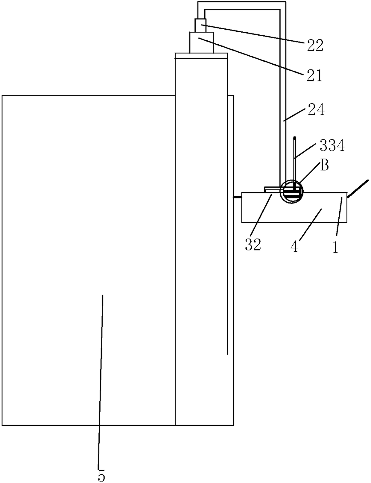
[0044] Specific embodiments: when the material is being ground between the three roller shafts 6, first control the drive cylinder 21 so that the piston rod 22 is fully extended, that is, the cutting device 3 is located above the main funnel 1, and is connected with the main funnel 1 There is no contact at all, so that the slurry can be output smoothly; the material that has completed the grinding work is formed into a slurry, which is rotated by the front roller and sent to the discharge port, and is scraped off and formed into a block under the action of the scraper. Main funnel 1 direction transmission, when the slurry is transmitted to the main funnel 1, control the driving cylinder 21 to work, the piston rod 22 descends, and drives the working rod 24 to descend, at this time the first scraper 32 cuts the slurry into sections as a whole, and the Simultaneously, the cutting device 3 at both ends is in contact with the slurry, that is, the first scraper 32 directly cuts off b...


PUM


Abstract

The invention discloses a three-roller grinding machine. The three-roller grinding machine comprises a main hopper matched with a discharge outlet of the three-roller grinding machine; a support plateparallel to the main hopper is arranged above the main hopper; a drive cylinder is arranged at the upper end of the support plate; a connection rod is fixed to and perpendicularly connected with a piston rod of the drive cylinder; working rods are fixed to the two ends of the connection rod and penetrate through the sliding support plate; a cut-off device for slurry separation is fixedly arrangedat the lower end of each working rod; storage tanks for storing separated slurry are arranged on the two sides of the main hopper; and each cut-off device is provided with a push mechanism for controlling the separated slurry to fall into the storage tanks. By means of the three-roller grinding machine, the large-grain-size slurry on the two sides can be separated and can further be collected smoothly, and no slurry is accumulated on the surface of the main hopper.

Description

technical field [0001] The invention relates to the field of paint production machinery, in particular to a three-roll grinder. Background technique [0002] The three-roll mill is mainly suitable for the manufacture of paint, ink, pigment, plastic and other slurries. The three-roller grinder achieves the grinding effect by extruding the surfaces of three horizontal rollers and friction at different speeds. After grinding, the material is scraped off by the scraper installed in front of the front roller. [0003] Because the rollers of the three-roll mill are difficult to control the temperature, pressure and other factors in the process of rolling the paint, the particle size of the paint on both sides of the discharge port of the grinder is different from the particle size of the paint in the middle; The particle size of the paint on both sides of the discharge port is larger than the particle size of the paint in the middle. If the paint with different particle sizes is ...

Claims


Application Information

Patent Timeline
Patent Type & Authority Applications(China)
IPC IPC(8): B02C4/28
CPCB02C4/28
Inventor 袁森吴航贺盟
Owner YANCHENG SHENYUAN PLASTIC
Learn More