Floating pay-off rack and pay-off device

A pay-off frame and shaft installation technology, which is applied in the field of floating pay-off racks and pay-off devices, can solve the problems of copper wire wear, failure to overcome copper wire wear, difficulty in ensuring the mutual alignment of pulleys and wire cages, etc., to achieve The effect of reducing friction

Pending Publication Date: 2018-11-13
山东中佳电子科技有限公司
View PDF10 Cites 1 Cited by
  • Summary
  • Abstract
  • Description
  • Claims
  • Application Information

AI Technical Summary

Problems solved by technology

The existing wire pulley is an ordinary pulley, which often jumps out of the groove due to the twisting of the wire in the wire cage; in addition, the bundled wire rack adopts multiple pulleys arranged side by side, and the copper wire often jumps out of the pulley due to the jump of the wire rod , and then cause problems such as broken wires or wire-to-wire entanglement, wire jamming, etc., which will stop production
[0003] The invention patent with the application number of 201420858653.9 discloses a multi-channel copper wire pay-off device, including a pay-off platform, and the pay-off platform is provided with a plurality of floating pay-off racks and bundled wire racks, and the floating pay-off rack and bundled wire racks There is also a wire support frame between the wire frames. The floating pay-off frame includes a trumpet-shaped wire barrel and a pulley. The pulley is installed on the mounting plate. The mounting plate is hinged with the pillar. The spiral comes out of the wire cage, passes upward through the guide cylinder, passes through the pulley, passes through the wire support frame in the horizontal direction, and then enters the cluster wire frame. In this way, when the copper wire enters the wire cylinder, the degree of freedom of the guide cylinder is small. It can only rotate along the Z axis, which will cause a certain degree of wear t

Method used


Image

  • Floating pay-off rack and pay-off device
  • Floating pay-off rack and pay-off device
  • Floating pay-off rack and pay-off device

Examples


Embodiment Construction

[0034] The principles and features of the present invention are described below in conjunction with the accompanying drawings, and the examples given are only used to explain the present invention, and are not intended to limit the scope of the present invention.

[0035] The structures, proportions, sizes, etc. shown in the drawings attached to this specification are only used to match the content disclosed in the specification for the understanding and reading of those who are familiar with this technology, and are not used to limit the conditions for the implementation of the present invention , so it has no technical substantive meaning, and any modification of structure, change of proportional relationship or adjustment of size shall still fall within the scope of the disclosure disclosed in the present invention without affecting the functions and objectives of the present invention. within the range covered by the technical content.

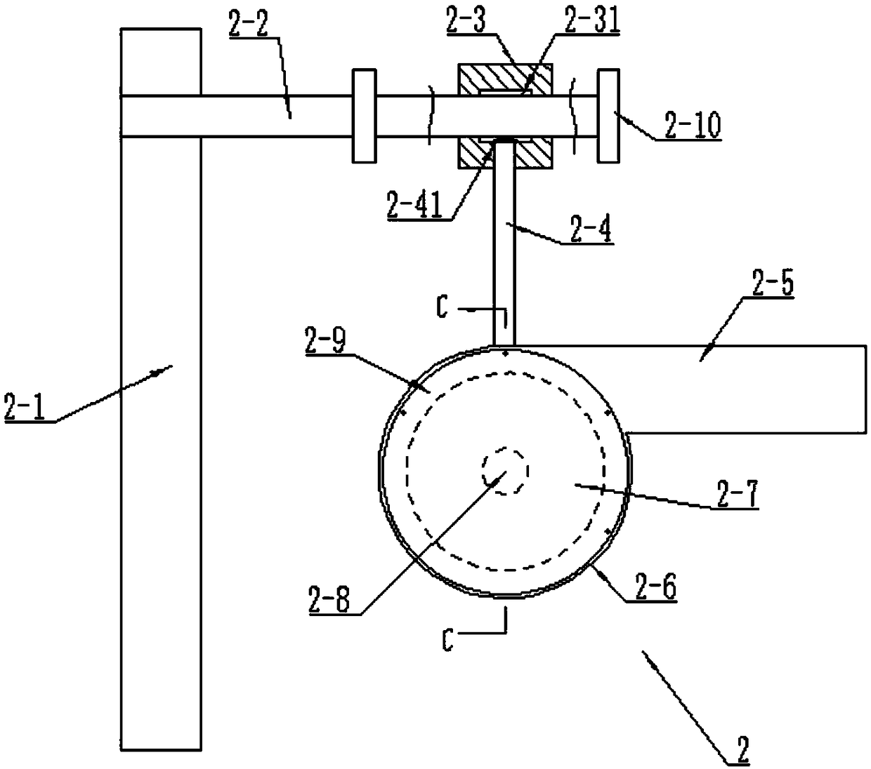
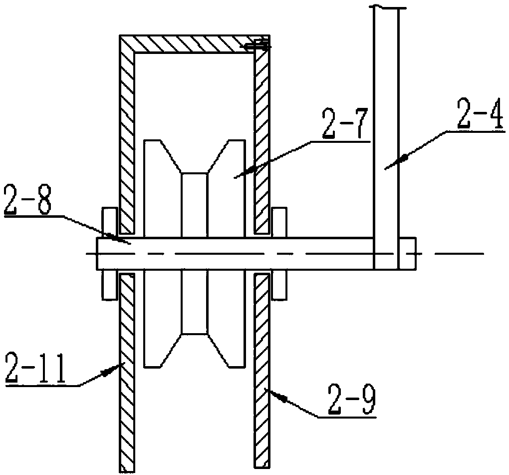
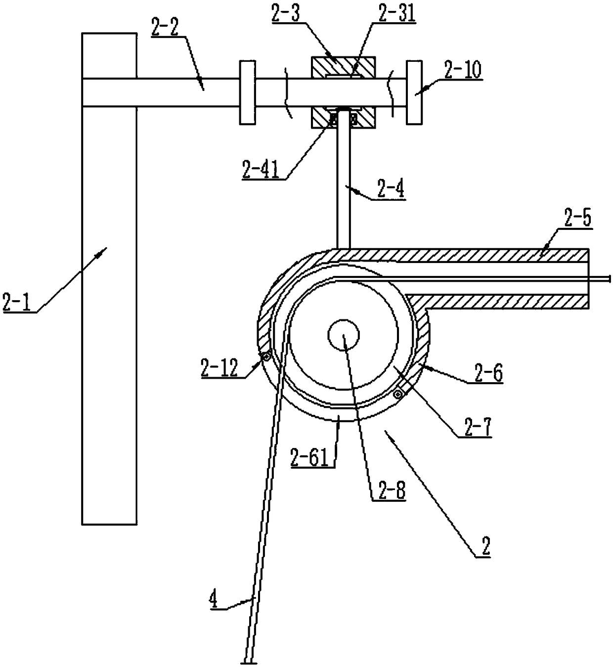
[0036] Such as Figure 1-Figure 3A...


PUM

PropertyMeasurementUnit
Central angleaaaaaaaaaa

Abstract

The invention relates to a floating pay-off rack. The floating pay-off rack comprises a column, a horizontal shaft arranged on the column, a bushing rotatably connected on the horizontal shaft in a sleeving manner and a pulley assembly arranged below the bushing. The pulley assembly comprises a pulley and a pulley mounting shaft, one end of the pulley mounting shaft is rotatably connected to the bushing through a connecting rod while the pulley is mounted at the other end of the pulley mounting shaft, the pulley is rotatably connected to the pulley mounting shaft, a protecting hood is also arranged on the outer side of the pulley, the protecting hood comprises a guide barrel, an arc-shaped barrel and a front baffle plate and a back baffle plate arranged at two ends of the arc-shaped barrel, the central axis of the guide barrel is aligned to the upper part of a pulley groove in height, and both the front baffle plate and the back baffle plate are rotatably connected to the pulley mounting shaft through bearings. The invention also relates to a multi-path pay-off device adopting the floating pay-off rack, so that wear of copper wires can be reduced to the maximum extent, the copper wires are prevented from intertwining, the problem of copper wire jumping is solved, and the production efficiency is improved.

Description

technical field [0001] The invention relates to a floating pay-off rack and a pay-off device, in particular to a floating pay-off rack and a pay-off device for drawing copper wires. Background technique [0002] In the copper wire production process, it is generally necessary to form a thin copper wire through large drawing, medium drawing and small drawing of the copper rod. In the middle drawing or small drawing process, usually a drawing machine has to draw multiple groups of copper wires at the same time, and the copper wires need to be unwound in front of the drawing machine and then sent to the drawing machine in bundles formed by a pay-off frame. Each single-ended wire needs to be pulled out in a spiral form from the wire cage, through the single-ended wire pulley, the wire support frame, and then to the bundled wire frame. The existing wire pulley is an ordinary pulley, which often jumps out of the groove due to the twisting of the wire in the wire cage; in addition...

Claims


Application Information

Patent Timeline
IPC IPC(8): B21C47/28B21C47/18
CPCB21C47/18B21C47/28
Inventor 赵钦海路京勇
Owner 山东中佳电子科技有限公司
Why Eureka
Try Eureka