Clamping fixture for turning thin-walled pipe

A technology of turning and pipe fittings, which is applied in the direction of metal processing machinery parts, manufacturing tools, metal processing equipment, etc., can solve the problems of reducing processing accuracy, the influence of processing the outer wall of pipe fittings, and increasing the cost of use, so as to improve work efficiency and processing accuracy , the effect of convenient operation

Inactive Publication Date: 2018-11-13
永春宏达工业设计有限公司
View PDF9 Cites 10 Cited by
  • Summary
  • Abstract
  • Description
  • Claims
  • Application Information

AI Technical Summary

Problems solved by technology

The utility model overcomes the technical defect that the existing thin-walled pipe fitting clamping device is easy to damage the outer wall of the thin-walled pipe fitting and cannot complete the processing of the thin-walled pipe fitting at one time, and provides a kind of thin-walled pipe fitting that is not easy to damage the outer wall and can make the thin-walled pipe fitting Thin-walled pipe fittings cylindrical processing fixture for one-time processing of pipe fittings
However, this fixture needs to be expanded and tightened by gas pressure, which requires an additional gas source, which increases the cost of use and is not easy to operate. At the same time, the mandrel of the fixture is clamped by a three-jaw chuck, which makes it easy to rotate the mandrel. The processing of the outer wall of the pipe will affect the processing accuracy

Method used


Image

  • Clamping fixture for turning thin-walled pipe
  • Clamping fixture for turning thin-walled pipe
  • Clamping fixture for turning thin-walled pipe

Examples


Embodiment 1

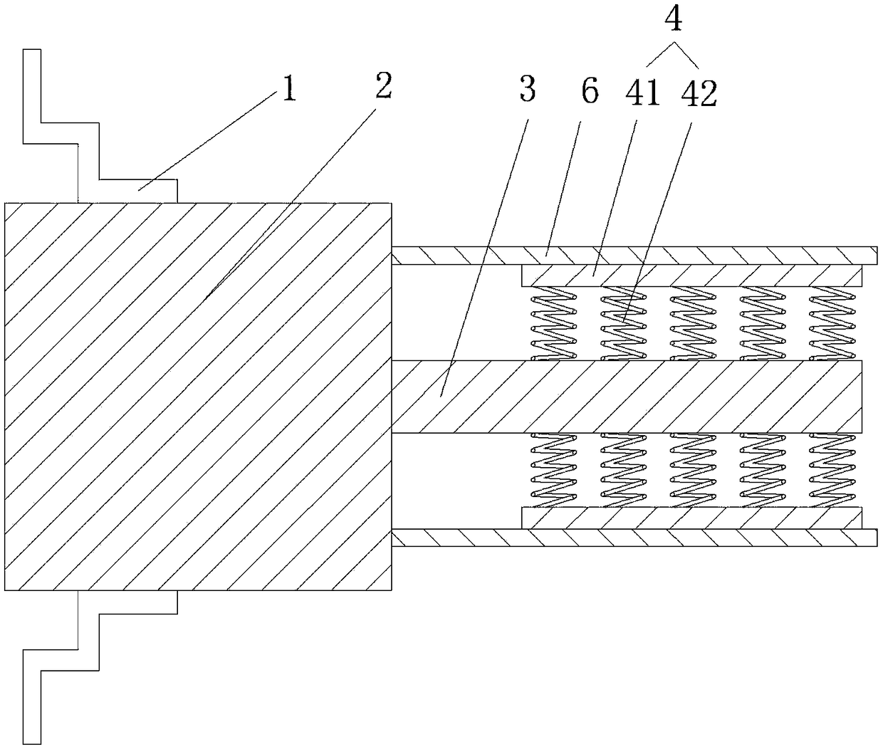
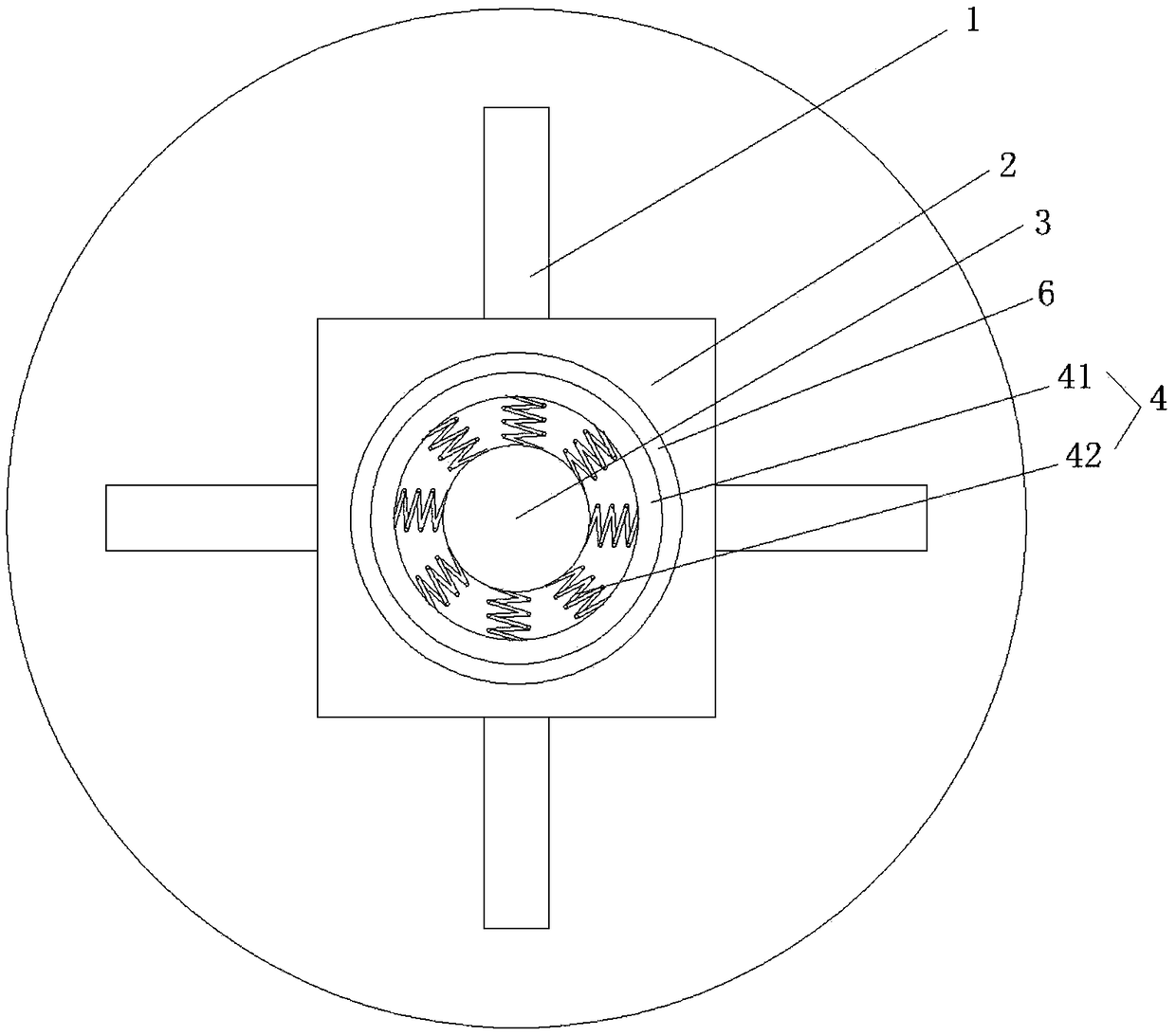
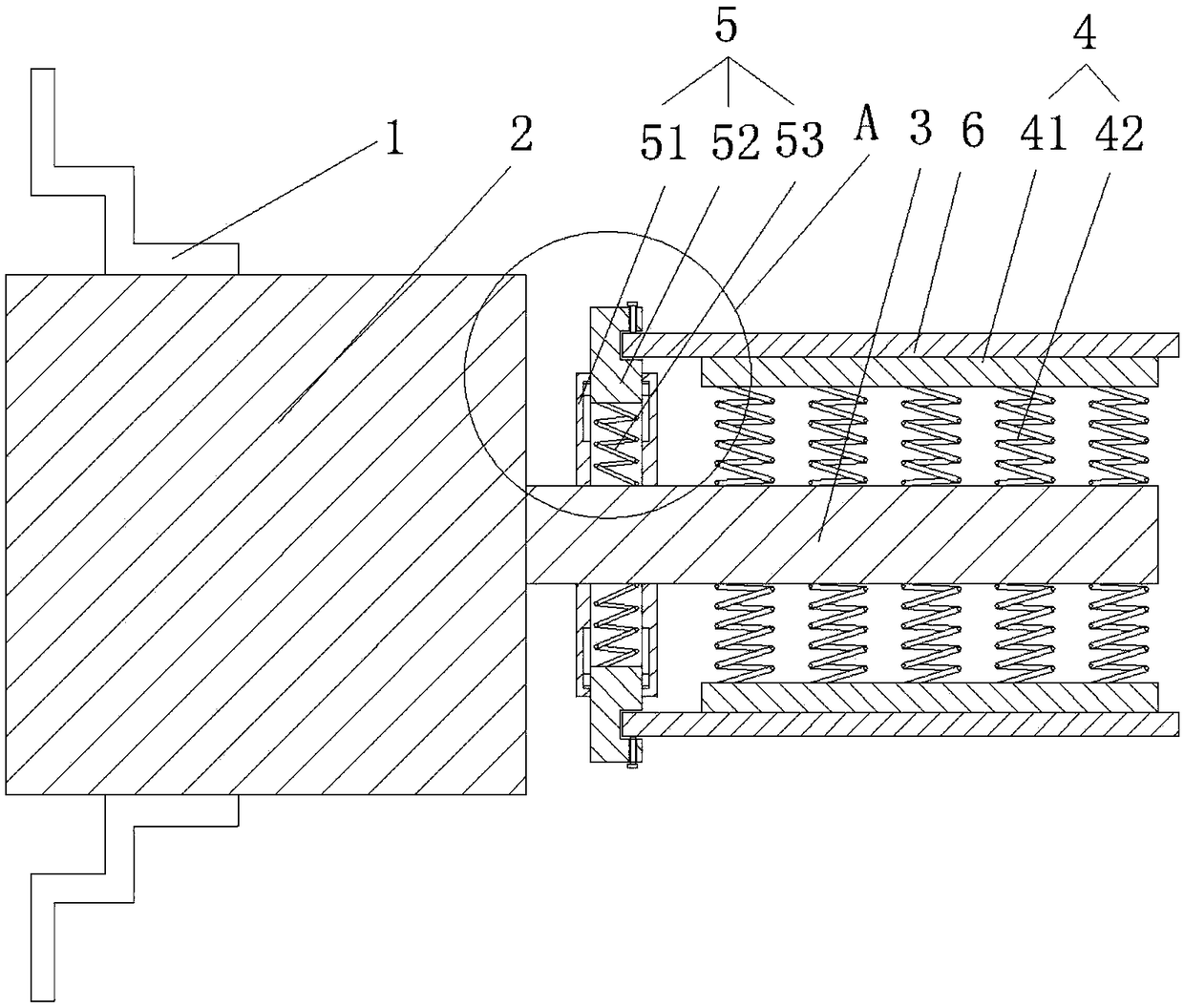
[0031] like image 3 As shown, the fixed shaft 3 and the fixed block 2 are integrally formed, and the fixed shaft 3 is provided with a clamping device 5 in the radial direction. The sliding groove 51, the sliding block 52 arranged in the sliding groove 51 and movable along the length direction of the sliding groove 51, and the sliding block 52 disposed in the sliding groove 51 along the length direction of the sliding groove 51 and used for connecting the sliding groove 51 and the sliding block 52 The tension spring 53 is provided on the sliding block 52 and the engaging groove 521 for engaging the pipe piece 6 is provided. The sliding slots 51 are integrally formed with the fixed shaft 3 , and there are four sliding slots 51 distributed in a circular array on the fixed shaft 3 , and are consistent with the distribution of the jaws of the four-jaw chuck 1 . The clamping device 5 can be clamped and adjusted according to the pipe fittings 6 of different diameters, and due to th...

Embodiment 2

[0034] like Figure 5 As shown, the fixed block 2 is movably connected with the fixed shaft 3, the fixed block 2 is provided with connecting holes 21 distributed axially along the fixed block 2, the connecting holes 21 are arranged on the axial center line of the fixed block 2, and the connecting holes 21 are provided with An internal thread, the outer surface of the fixed shaft 3 is provided with an external thread that cooperates with the internal thread. The fixed shaft 3 and the fixed block 2 are connected by threads, which can facilitate the installation and disassembly of the fixed shaft 3, and at the same time can ensure that the fixed shaft 3 and the fixed block 2 are located on the same central axis, and can also prevent the fixed shaft 3 from rotating and affect the machining accuracy. question.

[0035] As preferred, such as Image 6 As shown, the other end of the fixed block 2 corresponding to the connecting hole 21 is provided with a tapered hole 22 along the ax...


PUM


Abstract

The invention provides a clamping fixture for turning a thin-walled pipe, comprising a four-jaw chuck, a fixing block arranged in the four-jaw chuck, a fixing shaft arranged on the fixing block and distributed along the axial direction of the fixing block, and a jacking device arranged in the radial direction of the fixing shaft, wherein the jacking device comprises a jacking barrel coaxial with the fixing shaft, and compression springs connecting the inner wall of the jacking barrel with the outer wall of the fixing shaft, the diameter of the jacking barrel is greater than the diameter of thefixing shaft, the fixing block is a cube, and the axial center line of the fixing block coincides with the axial center line of the fixing shaft and the axial center line of the four-jaw chuck. Through arranging the jacking device, the thin-walled part can be more conveniently jacked better. At the same time, the fixing shaft for being connected with the jacking device is connected with the cubicfixing block, and the four-jaw chuck is used for fixing the fixing block, so that it is ensured that jacking acting force can be applied to the axial direction and the radial direction of the thin-walled part, and the machining precision is improved.

Description

technical field [0001] The invention relates to the technical field of fixtures for mechanical processing, in particular to a clamping fixture for machining thin-walled pipes. Background technique [0002] At present, in the production process of automation equipment, thin-walled pipe fittings are usually used, and in order to make the thin-walled pipe fittings better cooperate with other parts in the equipment, it is usually necessary to process the outer circle of the thin-walled pipe fittings. When the lathe is processing thin-walled pipe parts, referred to as thin-walled pipes, limited by the size of the jaws, sometimes it cannot be clamped firmly. At the same time, for thin-walled pipe parts, it is easy to cause deformation of the parts during clamping. During the high-speed rotating cutting process, the parts are prone to bending deformation and shaking, which is not conducive to ensuring the machining accuracy. Even for long thin-walled pipe parts, they cannot be proc...

Claims


Application Information

Patent Timeline
Patent Type & Authority Applications(China)
IPC IPC(8): B23Q3/12
CPCB23Q3/12
Inventor 章雪平
Owner 永春宏达工业设计有限公司
Why Eureka
Try Eureka