Automatic scanning detection equipment

A scanning detection and equipment technology, which is applied to conveyor control devices, conveyors, conveyor objects, etc., can solve the problems of high workload of workers, unfavorable stable production operations, low detection efficiency, etc., to improve the height adjustment effect. , Improve the effect of detection adjustability and detection range expansion

Inactive Publication Date: 2018-11-13
WUHU YUANMA AUTOMATION EQUIP CO LTD
View PDF0 Cites 0 Cited by
  • Summary
  • Abstract
  • Description
  • Claims
  • Application Information

AI Technical Summary

Problems solved by technology

[0002] In the production process, in order to ensure the reliability of the quality, the components and finished products of each equipment need to be strictly inspected, so as to ensure the service life of the overall structure. The usual inspection operation is manually placed at the corresponding inspection equipment. Further testing, the detection efficiency is low, and the work intensity of the staff is high, which is not conducive to the continuous testing operation of the product. For large-scale products that fail the inspection, it is difficult to carry out stable picking and offline operations. During the process, the staff is prone to fatigue, which reduces the detection accuracy, which is not conducive to the guarantee of product quality. At the same time, the detection efficiency is reduced, which is not conducive to the stable production operation

Method used


Image

  • Automatic scanning detection equipment
  • Automatic scanning detection equipment
  • Automatic scanning detection equipment

Examples


Embodiment Construction

[0014] In order to deepen the understanding of the present invention, the present invention will be further described below in conjunction with examples, which are only used to explain the present invention and do not constitute a limitation to the protection scope of the present invention.

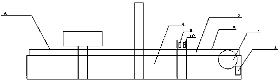
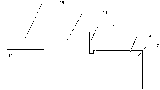
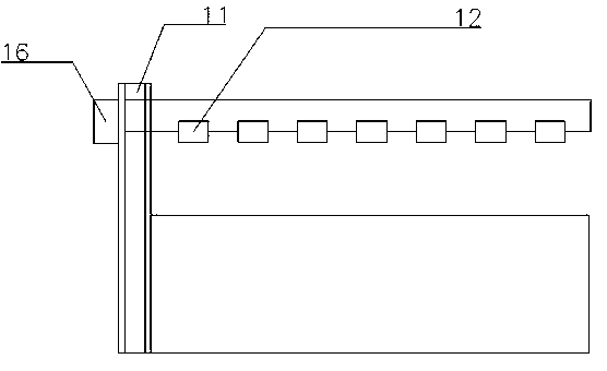
[0015] Such as figure 1 , 2 As shown in and 3, the present embodiment provides an automatic scanning detection equipment, including a transmission device, a push rod assembly and a scanning detection equipment, the push assembly includes a push plate 13, a piston rod 14 and a cylinder 15, the push plate 13, Piston rod 14 and cylinder 15 are connected sequentially, and described scanning detection equipment comprises elevating mechanism and at least one detection camera 12, and described elevating mechanism comprises transmission belt 11 and second motor 16, and described second motor 16 is arranged on frame 4, Described frame 4 is provided with crossbeam, and described crossbeam is conne...


PUM


Abstract

The invention provides automatic scanning detection equipment. The automatic scanning detection equipment comprises a conveying device, a push rod assembly and scanning detection equipment body. The conveying device is arranged on a machine frame, the conveying device comprises a first motor, a conveyor belt and a frequency converter, and the frequency converter is arranged on the machine frame. The first motor is connected with the frequency converter, the conveyor belt is provided with a detection inlet and a detection outlet, the scanning detection equipment body is arranged on one side ofthe conveyor belt, and the scanning detection equipment body is arranged between the detection inlet and the detection outlet. The push rod assembly is arranged at the left end of the scanning detection equipment body, the push rod assembly is arranged on the machine frame, a discharging guide rail is arranged opposite to the push rod assembly, the discharging guide rail is connected with the conveyor belt, baffles are arranged on the left side, the right side and the back side of the discharging guide rail, position detection equipment is arranged on one side of the conveyor belt, and the position detection equipment comprises a pressure sensor and a photoelectric sensor. The working efficiency is greatly improved, the adjustability of the equipment is improved, and the waste of labor isreduced.

Description

technical field [0001] The invention relates to a scanning detection device, in particular to an automatic scanning detection device. Background technique [0002] In the production process, in order to ensure the reliability of the quality, the components and finished products of each equipment need to be strictly inspected, so as to ensure the service life of the overall structure. The usual inspection operation is manually placed at the corresponding inspection equipment. Further testing, the detection efficiency is low, and the work intensity of the staff is high, which is not conducive to the continuous testing operation of the product. For large-scale products that fail the inspection, it is difficult to carry out stable picking and offline operations. During the process, the staff is prone to fatigue, which reduces the detection accuracy, which is not conducive to the guarantee of product quality. At the same time, the detection efficiency is reduced, which is not con...

Claims


Application Information

Patent Timeline
IPC IPC(8): B65G43/08B65G47/82
CPCB65G43/08B65G47/82B65G2203/041
Inventor 胡世珍
Owner WUHU YUANMA AUTOMATION EQUIP CO LTD
Why Eureka
Try Eureka